
Concept explainers
Videos
6-37* to 6-46* For the problem specified in the table, build upon the results of the original problem to determine the minimum factor of safety for fatigue based on infinite life, using the modified Goodman criterion. The shaft rotates at a constant speed, has a constant diameter, and is made from cold-drawn AISI 1018 steel.
| Problem Number | Original Problem, Page Number |
| 6-42* | 3–73, 152 |
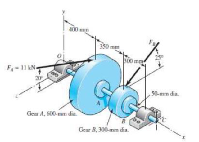
3-72* to 3-73* A gear reduction unit uses the countershaft shown in the figure. Gear A receives power from another gear with the transmitted force FA applied at the 20° pressure angle as shown. The power is transmitted through the shaft and delivered through gear B through a transmitted force FB at the pressure angle shown.
- (a) Determine the force FB assuming the shaft is running at a constant speed.
- (b) Find the bearing reaction forces, assuming the bearings act as simple supports.
- (c) Draw shear-force and bending-moment diagrams for the shaft. If needed, make one set for the horizontal plane and another set for the vertical plane.
- (d) At the point of maximum bending moment, determine the bending stress and the torsional shear stress.
- (e) At the point of maximum bending moment, determine the principal stresses and the maximum shear stress.
The minimum factor of safety for fatigue based on infinite life.
Answer to Problem 42P
The minimum factor of safety for fatigue based on infinite life is
Explanation of Solution
The figure below shows the free body diagram of pulley A.
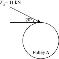
Figure-(1)
The figure below shows the free body diagram of pulley B.
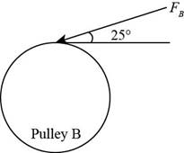
Figure-(2)
Calculate the force
Here, the force acting on pulley
Write the moment about bearing
Here, the reaction force at bearing
Write the equation to balance the forces in
Here, the reaction force at bearing
Write the moment about bearing
Here, the reaction force at bearing
Write the equation to balance the forces in
Here, the reaction force at bearing
Calculate the reaction forces at bearing
Here, the reaction force at bearing
Calculate the reaction forces at bearing
Here, the reaction force at bearing
The calculations for shear force and bending moment diagram in
Calculate the shear force at
Here, the shear force at
Calculate the shear force at
Here, the shear force at
Calculate the shear force at
Here, the shear force at
Calculate the shear force at
Here, the shear force at
Calculate the moment at
Here, the moment at
Calculate the moment at
Here, the moment at
Calculate the moment at
Here, the moment at
Write the net moment at
Here, the net moment at
Write the net moment at
Here, the net moment at
Write the torque transmitted by shaft from
Here, the torque transmitted by shaft from
Calculate the bending stress.
Here, the bending stress is
Calculate the shear stress.
Here, the shear stress is
Write the expression for von Mises alternating stress.
Here, the amplitude component of the axial stress is
Write the expression for von Mises mid-range stress.
Here, the mid-range component of the axial stress is
Write the expression for von Mises maximum stress.
Here, the maximum component of the axial stress is
Write the expression for yield factor of safety.
Here, the yield strength of the material is
Write the expression for endurance limit for test specimen.
Here, the minimum tensile strength is
Write the surface factor for the countershaft.
Here, the constants for surface factor are
Write the size factor for the countershaft.
Write the endurance limit at the critical location of the machine part.
Write the modified Goodman equation.
Here, the fatigue factor of safety is
Conclusion:
Substitute
Substitute
Substitute
Substitute
Substitute
Substitute
Substitute
Substitute
Substitute
Substitute
Substitute
Substitute
Substitute
Thus, the shear force and bending moment diagram in
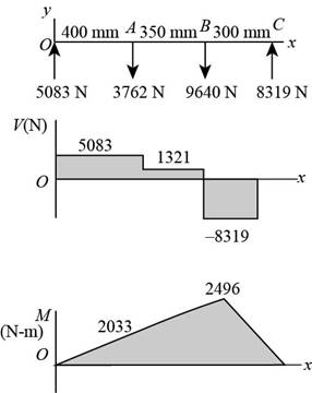
Figure-(4)
Substitute
Substitute
Substitute
Substitute
Substitute
Substitute
The shear force and bending moment diagram in
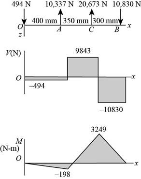
Figure-(5)
Substitute
Substitute
Since
Substitute
Substitute
Substitute
Substitute
Substitute
Substitute
Refer to the Table A-20 “Deterministic ASTM Minimum Tensile and Yield Strengths for Some Hot-Rolled (HR) and Cold-Drawn (CD) Steels” to obtain the yield strength as
Substitute
Substitute
Refer to Table 6-2 “Parameters for Marin Surface Modification Factor” to obtain
Substitute
Substitute
Substitute
Substitute
Thus, the minimum factor of safety for fatigue based on infinite life is
Want to see more full solutions like this?
Chapter 6 Solutions
Shigley's Mechanical Engineering Design (McGraw-Hill Series in Mechanical Engineering)


- From dynamics CHAPTER 12: Rectilinear Kinematics. Continuous Motion. Qu. 1 The velocity of a particle traveling along a straight line is v = (3t2 - 6t)ft/s, where t is in seconds. If s = 4ft when t = 0, determine the position of the particle when t = 4s. What is the total distance traveled during the time interval t = 0 to t = 4s? Also, what is the acceleration when t = 2 s?I want to show all work step by step problemsarrow_forwardZ1 please help on the attached question.arrow_forwardProblem 3 (10 pts). When using linear shape functions to solve the multiphysics thermoelastic problem considered in class, we found that the stress in the rod is affected by unphysical oscillations like the following plot(a) [10pts] What is the origin of this issue and how can we fix it?arrow_forward
- Z2 please help on the attached question.arrow_forwardB2 Please help on the attached question.arrow_forwardA particle, starting from rest, travels along a straight track and for 14 s has an acceleration as shown. Draw the v-t graph that describes the motion and find the distance traveled in 14 S. a 8 11 уг (0.8) 11 ут (6,8 6. 4+ 2 *2 Ye (1.0) t 2 4 6 8 10 12 14 dre dec dec decarrow_forward
 Elements Of ElectromagneticsMechanical EngineeringISBN:9780190698614Author:Sadiku, Matthew N. O.Publisher:Oxford University Press
 Mechanics of Materials (10th Edition)Mechanical EngineeringISBN:9780134319650Author:Russell C. HibbelerPublisher:PEARSON
 Thermodynamics: An Engineering ApproachMechanical EngineeringISBN:9781259822674Author:Yunus A. Cengel Dr., Michael A. BolesPublisher:McGraw-Hill Education
 Control Systems EngineeringMechanical EngineeringISBN:9781118170519Author:Norman S. NisePublisher:WILEY
 Mechanics of Materials (MindTap Course List)Mechanical EngineeringISBN:9781337093347Author:Barry J. Goodno, James M. GerePublisher:Cengage Learning
 Engineering Mechanics: StaticsMechanical EngineeringISBN:9781118807330Author:James L. Meriam, L. G. Kraige, J. N. BoltonPublisher:WILEY