
Concept explainers
Find the slope
Answer to Problem 33P
The slope
The deflection
The slope
The deflection
Explanation of Solution
Given information:
The Young’s modulus (E) is 29,000 ksi.
The moment of inertia (I) is
Calculation:
Consider flexural rigidity EI of the beam is constant.
Show the free body diagram of the given beam as in Figure (1).
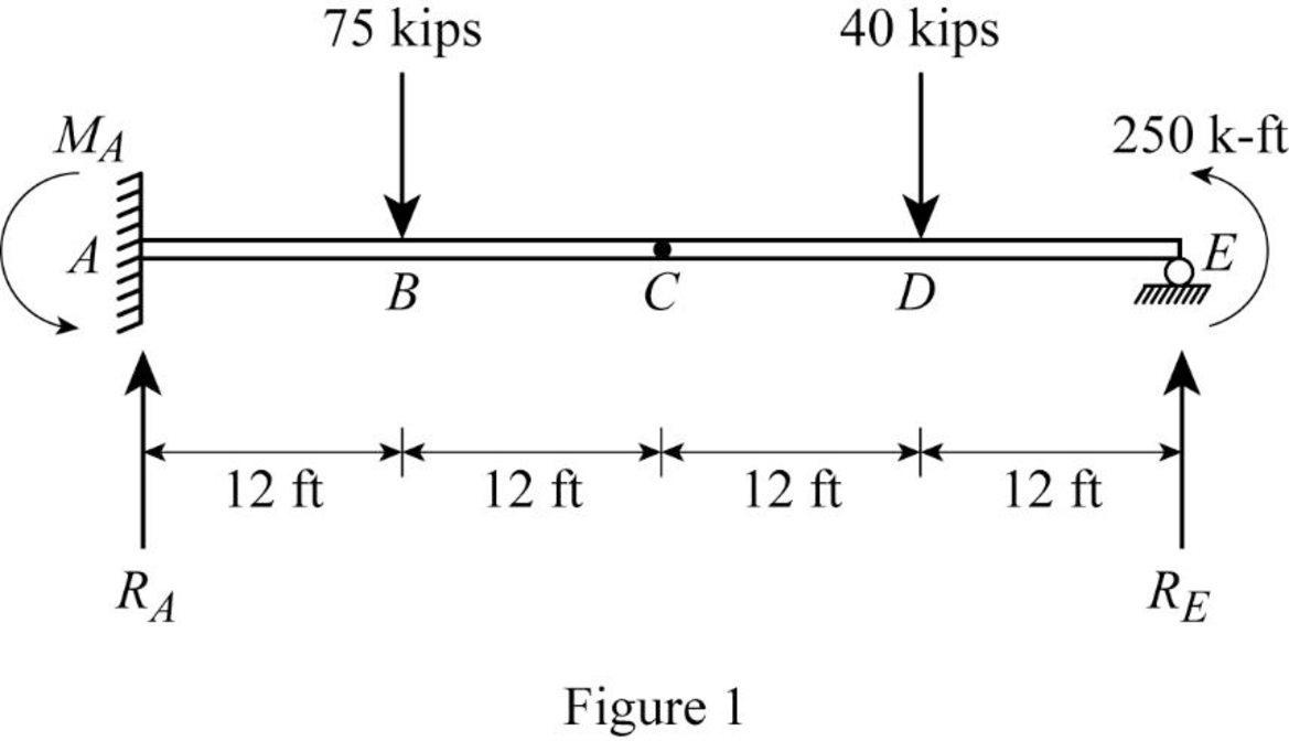
Refer Figure (1),
Consider upward is force is positive and downward force is negative.
Consider clockwise moment is negative and counterclockwise moment is positive.
Split the given beam into two sections such as AC and CE.
Consider the portion CE:
Draw the free body diagram of the portion CE as in Figure (2).
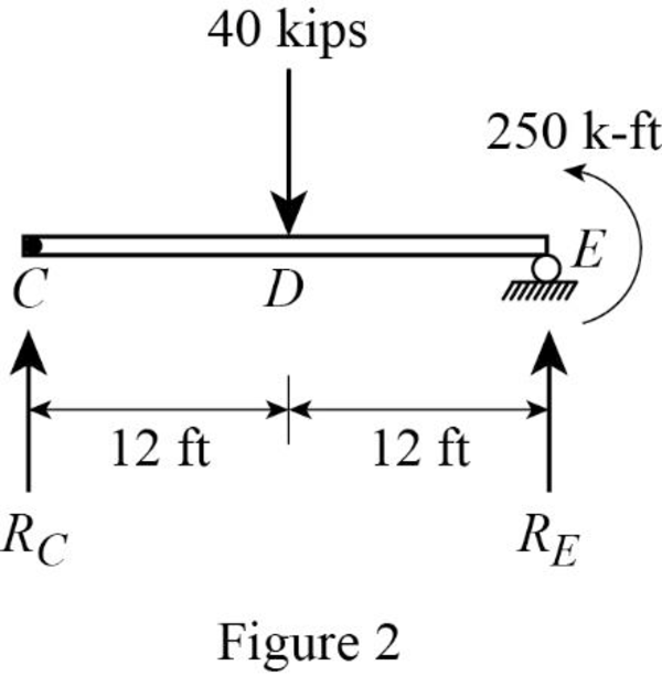
Refer Figure (2),
Consider a reaction at C and take moment about point C.
Determine the reaction at E;
Determine the reaction at support A;
Show the reaction of the given beam as in Figure (3).
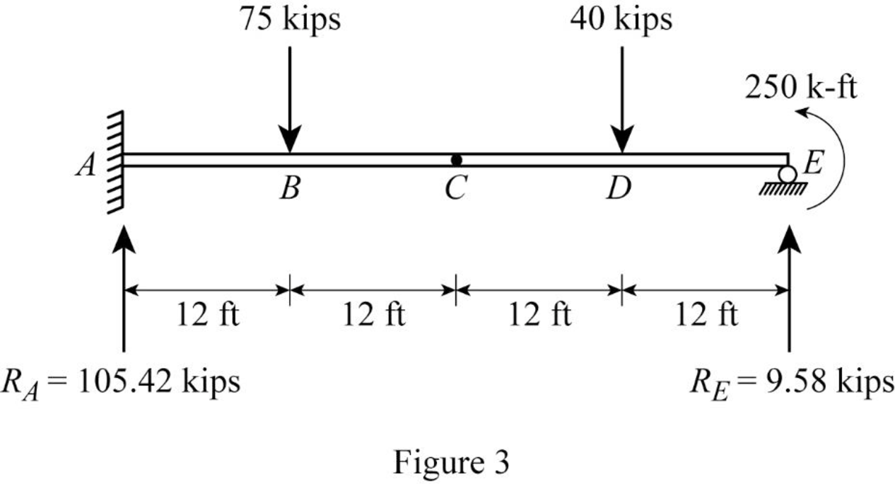
Refer Figure (3),
Determine the moment at A:
Determine the bending moment at B;
Determine the bending moment at C;
Determine the bending moment at D;
Determine the bending moment at E;
Show the
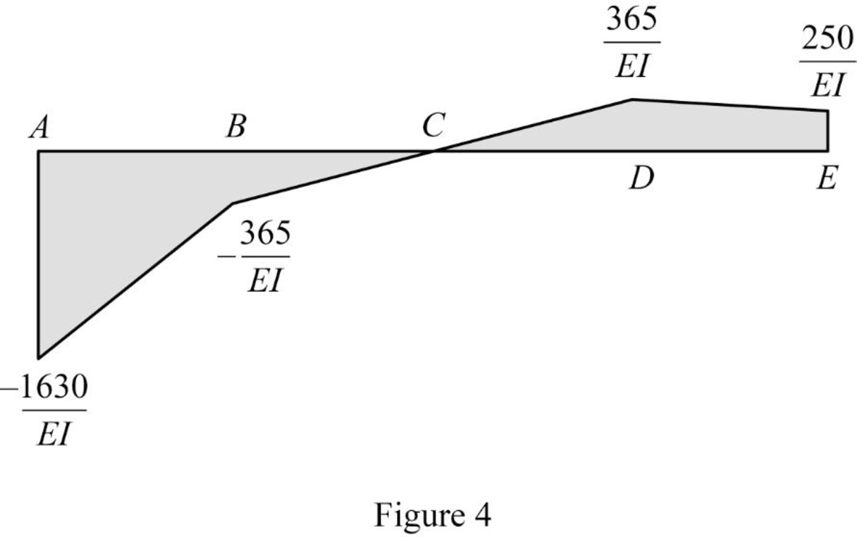
Show the elastic curve diagram as in Figure (5).
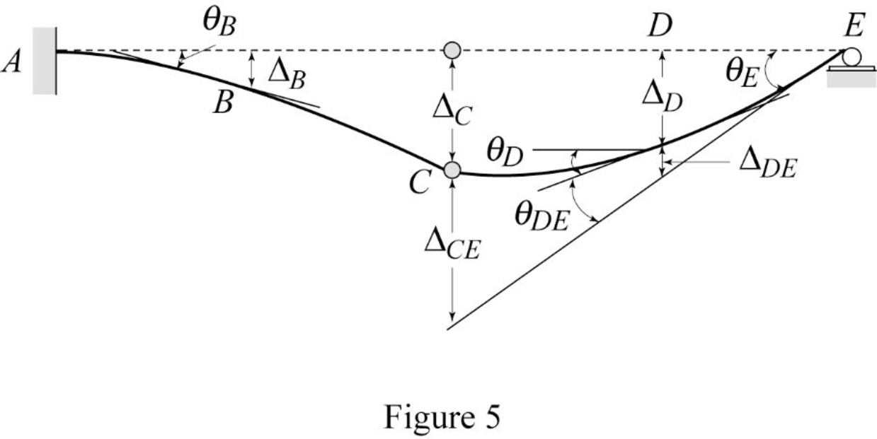
Refer Figure (4),
Determine the slope at B;
Here, b is the width and h is the height of respective triangle.
Substitute 12 ft for
Substitute 29,000 ksi for E and
Hence, the slope at B is
Determine the deflection between A and B using the relation;
Here,
Substitute 12 ft for
Substitute 29,000 ksi for E and
Hence, the deflection at B is
To determine the slope at point E, it is necessary to determine the deflection at point C and the deflection between C and E.
Determine the deflection at C and A using the relation;
Substitute 12 ft for
Determine the deflection between C and E using the relation;
Substitute 12 ft for
Determine the slope at E using the relation;
Here,
Substitute
Determine the slope between D and E using the relation;
Here, b is the width and h is the height of respective triangle.
Substitute 12 ft for
Determine the slope at D using the relation;
Substitute
Substitute 29,000 ksi for E and
Hence, the slope at D is
Determine the deflection between D and E using the relation;
Here, b is the width and h is the height of respective rectangle and triangle.
Substitute 12 ft for
Determine the deflection at D using the relation;
Substitute 12 ft for
Substitute 29,000 ksi for E and
Hence, the deflection at point D is
Want to see more full solutions like this?
Chapter 6 Solutions
Structural Analysis, 5th Edition
- The city's downtown area on Elm St, with its intricate network of roads and intersections, has long been a challenge for both seasoned travelers and newcomers alike. Given the lane configurations for the shown intersection, find the number of conflict points. Vehicle-to-vehicle conflicts (merge, diverge, and/or crossing conflicts) Vehicle-to-pedestrian conflicts Vehicle-to-bicycle conflictsarrow_forwardCan you please do hand calcs and breakdown each steparrow_forwardQ4. Statically determinate or indeterminate frame analysis by the stiffness method a) Determine the stiffness matrix of the frame as shown in Fig. 4. Nodes 1 and 3 are fixed supports. Assume I = 300(10%) mm, A = 10(103) mm², E = 200 GPa for each member. Indicate the degrees-of freedom in all the stiffness matrices. Use the values of L3-3.5 m, w = 24 kN/m and P = 30 kN. Note, L4-1.8L3 (i.e. 1.8 times L3). b) Determine all the displacement components at node 2 and all internal reactions at node 2. Show all calculations. c) Draw the BMD of the frame on the compression side showing all the salient values. Show all calculations. d) Repeat the problem using the Strand 7. Show the model with all the nodes and element numbers and boundary conditions. Submit a hard copy from Strand7 showing all the reactions (highlight these in the hard copy). Display the bending moment diagram for the frame. 4 e) Compare the BMD from Strand 7 with the theoretical one and compare the respective values of…arrow_forward
- Can you please break down all the hand calcs and make sure we answer the below. a Determine the global stiffness matrices (k’) of all truss members including correct degrees-of freedom (dof)-3x3 b Determine the global stiffness matrix (K) of the whole truss (include dof numbers) c i) Calculate vectors D and Q (4+4). ii) Show partition and solve KD=Q iii) Calculate all the member forces d i) Solve the problem using Strand7 (model) (You must model the beam property as truss) ii) Display of deflected shape, nodal displacements and member forces (3+3+3) e Comparison of member forces and comments , comparison of displacemnts and commnetsarrow_forwardYOU HAVE A UNIFORM SUBGRADE ELEVATION FOR YOUR BUILDING FOUNDATION THAT HASBEEN VERIFIED. YOUR SLAB IS DESIGNED TO BE 12 INCHES THICK.USING THE GIVENDIMENSIONS AROUND THE PROPOSED BUILDING FOUNDATION, CALCULATE THE CUBIC FEETAND THE CUBIC YARDS OF CONCRETE NEEDED FOR THE FOUNDATION **Sketch Attached**arrow_forwardWHAT ARE THE COORDINATES (N,E) AT POINT A AND POINT B IN THE SKETCH (ATTACHED)arrow_forward
- Can you please do with hand calcs and answer the following: a Determine the global stiffness matrix (K) of the beam including indicating correct degrees-of freedom (dof) b i) Calculate vectors D and Q ii) Show partition and solve KD=Q for D iii) Calculate all reactions c BMD & max BM, deflected shape d i) Solve the problem using Strand7 (model) ii) Display the deflected shape and BMD e Comparisons of reactions + Max BM including commentsarrow_forward5-1. Determine the force in each member of the truss, and state if the members are in tension or compression.arrow_forwardI have the correct answer provided, just lookng for a more detailed breadown of how the answer was obtained thanks.arrow_forward
- Q1. Statically indeterminate beam analysis. a) Calculate the BMs (bending moments) at all the joints of the beam shown in Fig.1 using the moment distribution method. The beam is subjected to an UDL of w kN/m. L1= 0.4L. Assume the support at C is pinned, and A and B are roller supports. E = 200 GPa, I=250x106 mm². Use the values of w = 50 kN/m and L = 6 b) Draw the shear force and bending diagrams for the entire beam. c) Calculate the BMs at all the joints of the same beam shown in Fig.1 using the slope deflection method. d) Compare the values of BMs obtained using the two methods a) and c) and comment. w kN/m £1m Lm m Fig 1. Beam for Q1arrow_forwardI have the answer provided for the question, just looking for a more detailed breadown of how it was obtained thanks.arrow_forwardQ5.--Finite-element-modelling. a) → Draw-a-2D-element-and-show-the dots (degrees of freedom). Draw-all-the-2D-elements. used-in-Strand 7..Explain the differences between-these-elements-in-terms-of-the-no..of. nodes-and-interpolation/shape-functions used. b)→A-8-m-x-8-m-plate (in-the-xx-plane)-with-8-mm-thickness, is fixed-at-all-the-edges.and.is. loaded-by-a-pressure-loading-of-4 kN/m2.-in-the-downward-(-2)-direction.-The-plate.is. made-of-steel-(E=-200 GPa, density-7850-kg/m3). Explain-the-steps-involved-in-setting. up-a-Strand 7-model-for-this-problem. Your-explanation-should-include-how-the-given. input-data-for-this-problem-will-be-used-in-Strand 7-modelling. Explain how you would. determine the maximum-deflection-from-the-Strand 7-output.-1 11arrow_forward
