
INTERNATIONAL EDITION---Engineering Mechanics: Statics, 14th edition (SI unit)
14th Edition
ISBN: 9780133918922
Author: Russell C. Hibbeler
Publisher: PEARSON
expand_more
expand_more
format_list_bulleted
Videos
Textbook Question
Chapter 5.4, Problem 57P
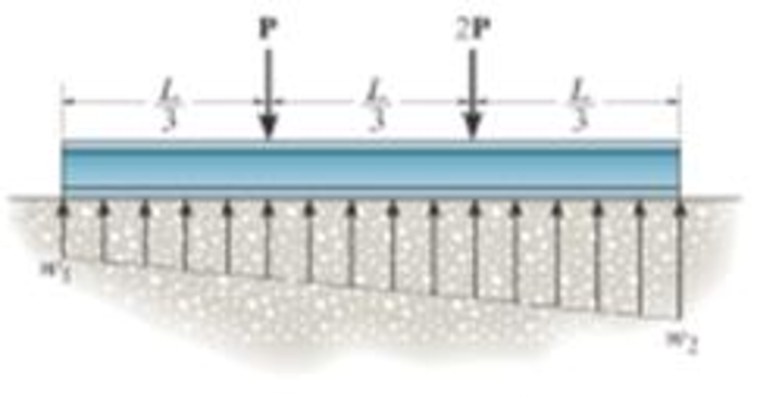
Assuming that the foundation exerts a linearly varying load distribution on its bottom, determine the load intensities w1, and w2 for equilibrium if P = 500 lb and L = 12 ft.
Prob. 5-57
Expert Solution & Answer

Learn your wayIncludes step-by-step video

schedule03:23
Students have asked these similar questions
Using method of joints, determine the force in each
member of the truss and state if the members are in
tension or compression.
A
E
6 m
D
600 N
4 m
B
4 m
900 N
Question 5.
The diagram below shows a mass suspended from a tie supported by two horizontal braces of
equal length. The tie forms an angle "a" of 60° to the horizontal plane, the braces form an angle
0 of 50° to the vertical plane.
If the mass suspended is 10 tonnes, and the braces are 10m long, find:
a) the force in the tie; &
b) the force in the braces
Horizontal Braces,
Tie
Mass
=
MMB 241 Tutorial 2.pdf
1 / 3
75%
+ +
Tutorial z
Topic: Kinematics of Particles:-.
QUESTIONS
1. Use the chain-rule and find y and ŷ in terms of x, x and x if
a) y=4x²
b) y=3e
c) y = 6 sin x
2. The particle travels from A to B. Identify the three unknowns, and write the three
equations needed to solve for them.
8 m
10 m/s
30°
B
x
3. The particle travels from A to B. Identify the three unknowns, and write the three
equations needed to solve for them.
A
40 m/s
20 m
B
1
Chapter 5 Solutions
INTERNATIONAL EDITION---Engineering Mechanics: Statics, 14th edition (SI unit)
Ch. 5.2 - Draw the free-body diagram for the following...Ch. 5.2 - Draw the free-body diagram for the following...Ch. 5.2 - Draw the free-body diagram for the following...Ch. 5.2 - Draw the free-body diagram for the following...Ch. 5.2 - Draw the free-body diagram for the following...Ch. 5.2 - Draw the free-body diagram for the following...Ch. 5.2 - Draw the free-body diagram for the following...Ch. 5.2 - Draw the free-body diagram for the following...Ch. 5.2 - Draw the free-body diagram for the following...Ch. 5.4 - Draw the free body diagram of each object. Prob....
Ch. 5.4 - Determine the horizontal and vertical components...Ch. 5.4 - Determine the horizontal and vertical components...Ch. 5.4 - The truss is supported by a pin at A and a roller...Ch. 5.4 - Determine the components of reaction at the fixed...Ch. 5.4 - The 25 kg bar has a center of mass at G. If it is...Ch. 5.4 - Determine the reactions at the smooth contact...Ch. 5.4 - Determine the components of the support reactions...Ch. 5.4 - Determine the reactions at the supports. Prob....Ch. 5.4 - Determine the horizontal and vertical components...Ch. 5.4 - Determine the reactions at the supports. Prob....Ch. 5.4 - Determine the reactions at the supports. Prob....Ch. 5.4 - Determine the reactions at the supports. Prob....Ch. 5.4 - Determine the tension in the cable and the...Ch. 5.4 - The man attempts to a up port the toad of boards...Ch. 5.4 - Determine the components of reaction at the...Ch. 5.4 - The man has a weight W and stands at the center of...Ch. 5.4 - A uniform glass rod having a length L is placed in...Ch. 5.4 - The uniform rod AB has a mass of 40 kg. Determine...Ch. 5.4 - If the intensity of the distributed load acting on...Ch. 5.4 - If the roller at A and the pin at B can support a...Ch. 5.4 - The relay regulates voltage and current. Determine...Ch. 5.4 - Determine the reactions on the bent rod which is...Ch. 5.4 - The mobile crane is symmetrically supported by two...Ch. 5.4 - Determine the reactions acting on the smooth...Ch. 5.4 - A linear torsional spring deforms such that an...Ch. 5.4 - Determine the force P needed to pull the 50-kg...Ch. 5.4 - Determine the magnitude and direction of the...Ch. 5.4 - The operation of the fuel pump for an automobile...Ch. 5.4 - Determine the magnitude of force at the pin A and...Ch. 5.4 - The dimensions of a jib crane, which is...Ch. 5.4 - The dimensions of a jib crane, which is...Ch. 5.4 - The smooth pipe rests against the opening at the...Ch. 5.4 - The beam of negligible weight is supported...Ch. 5.4 - The cantilevered jib crane is used to support the...Ch. 5.4 - The cantilevered jib crane is used to support the...Ch. 5.4 - The bar of negligible weight is supported by two...Ch. 5.4 - Determine the stiffness k of each spring so that...Ch. 5.4 - The bulk head AD Is subjected to both water and...Ch. 5.4 - The boom supports the two vertical loads. Neglect...Ch. 5.4 - The boom is intended to support two vertical loads...Ch. 5.4 - The 10-kg uniform rod is pinned at end A. If It is...Ch. 5.4 - If the truck and its contents have a mass of 50 kg...Ch. 5.4 - Three uniform books each having a weight W and...Ch. 5.4 - Determine the reactions at the pin A and the...Ch. 5.4 - If rope BC will fail when the tension becomes 50...Ch. 5.4 - The rigid metal strip of negligible weight is used...Ch. 5.4 - The rigid metal strip of negligible weight is used...Ch. 5.4 - The cantilever footing is used to support a wail...Ch. 5.4 - The uniform beam has a weight Wand length l and is...Ch. 5.4 - A boy stands out at the end of the diving board,...Ch. 5.4 - The 30-N uniform rod has a length of l = 1 m. If s...Ch. 5.4 - The uniform rod has a length I and weight W. It is...Ch. 5.4 - I he uniform rod of length L and weight W is...Ch. 5.4 - Assuming that the foundation exerts a linearly...Ch. 5.4 - Assuming that the foundation exerts a linearly...Ch. 5.4 - If it is also subjected to a couple moment of 100...Ch. 5.4 - Determine the distance d for placement of the load...Ch. 5.4 - If d = 1 m, and = 30, determine me normal...Ch. 5.4 - The man attempts to pull the tour wheeler up the...Ch. 5.4 - Where is the best place to arrange most of the...Ch. 5.7 - Draw the free-body diagram of each object.Ch. 5.7 - In each case, write the moment equations about the...Ch. 5.7 - The uniform plate has a weight of 500 lb....Ch. 5.7 - Determine the reactions at the roller support A,...Ch. 5.7 - The rod is supported by smooth journal bearings at...Ch. 5.7 - Determine the support reactions at the smooth...Ch. 5.7 - Determine the force developed in the short link...Ch. 5.7 - Determine the components of reaction that the...Ch. 5.7 - Determine the tension each rope and the force that...Ch. 5.7 - If these components have weights WA = 45000 Wa =...Ch. 5.7 - Determine the components of reaction at the fixed...Ch. 5.7 - Determine the vertical reactions at the wheels C...Ch. 5.7 - Determine the components of reaction at A, the...Ch. 5.7 - Determine the tension in each of the three...Ch. 5.7 - Determine the components of reaction at hinges A...Ch. 5.7 - Determine me tension in each cable and the...Ch. 5.7 - The cables are attached to a smooth collar ring at...Ch. 5.7 - Determine the components of reaction at the...Ch. 5.7 - Determine the components of reaction at the...Ch. 5.7 - Determine the components of reaction at the...Ch. 5.7 - Determine the magnitude of F which will cause the...Ch. 5.7 - Determine the components of reaction at A and the...Ch. 5.7 - Determine the components of reaction at these...Ch. 5.7 - Determine the components or reaction at these...Ch. 5.7 - Compute the x, y, z components of reaction at the...Ch. 5.7 - Determine the magnitude of F2 which will cause the...Ch. 5.7 - At A the connection is with a ball-and-socket....Ch. 5.7 - If it is supported by a ball-and-socket joint at C...Ch. 5.7 - Determine the x, y, z components of reaction at...Ch. 5.7 - Determine the horizontal tension T in the belt on...Ch. 5.7 - Determine the horizontal tension T in the belt on...Ch. 5.7 - Determine the components of reaction at A and the...Ch. 5.7 - If the roller at 8 can sustain a maximum load of 3...Ch. 5.7 - Determine the reactions at the supports A and B...Ch. 5.7 - Determine the normal reaction at the roller A and...Ch. 5.7 - Determine the horizontal and vertical components...Ch. 5.7 - Determine the x, y, z components of reaction at...Ch. 5.7 - Determine the horizontal equilibrium force P that...Ch. 5.7 - Determine the x, y, z components of reaction at...Ch. 5.7 - Determine the x and z components of reaction at...
Additional Engineering Textbook Solutions
Find more solutions based on key concepts
How is the hydrodynamic entry length defined for flow in a pipe? Is the entry length longer in laminar or turbu...
Fluid Mechanics: Fundamentals and Applications
What is the importance of modeling in engineering? How are the mathematical models for engineering processes pr...
HEAT+MASS TRANSFER:FUND.+APPL.
Which of the following statements will cause an error? a. x = 17 b. 17 = x c. x = 99999 d. x = '17'
Starting Out with Python (4th Edition)
Code an SQL statement that creates a table with all columns from the parent and child tables in your answer to ...
Database Concepts (8th Edition)
Look at the following pseudocode class definitions: Class Vegetable Public Module message () Display Im a veget...
Starting Out with Programming Logic and Design (5th Edition) (What's New in Computer Science)
What values are returned by each of the following? a. Math.round (2.3) b. Math.round (2.7) c. Math.floor (2.3) ...
Java: An Introduction to Problem Solving and Programming (8th Edition)
Knowledge Booster


Learn more about
Need a deep-dive on the concept behind this application? Look no further. Learn more about this topic, mechanical-engineering and related others by exploring similar questions and additional content below.Similar questions
- 3 m³/s- 1 md 45° V 1.8 mr 2mrarrow_forward= MMB 241 Tutorial 2.pdf 3/3 75% + + 6. A particle is traveling along the parabolic path y = 0.25 x². If x = 8 m, vx=8 m/s, and ax= 4 m/s² when t = 2 s, determine the magnitude of the particle's velocity and acceleration at this instant. y = 0.25x² -x 7. Determine the speed at which the basketball at A must be thrown at the angle of 30° so that it makes it to the basket at B. 30° -x 1.5 m B 3 m -10 m- 8. The basketball passed through the hoop even though it barely cleared the hands of the player B who attempted to block it. Neglecting the size of the ball, determine the 2arrow_forwardAdhesives distribute loads across the interface, whereas fasteners create areas of localized stresses. True or Falsearrow_forward
- A continuous column flash system is separating 100 kmol/h of a saturated liquid feed that is 45 mol% methanol and 55 mol% water at 1.0 atm. Operate with L/V = 1.5 and the outlet bottoms at xN = 0.28. Find the values of FL, FV, y1, and the number of equilibrium stages required. Find the value of Q used to vaporize FV. For a normal flash with the same feed and the same V/F, find the values of x and y.arrow_forwardA beer still is being used to separate ethanol from water at 1.0 atm. The saturated liquid feed flow rate is F = 840.0 kmol/h. The feed is 44.0 mol% ethanol. The saturated vapor steam is pure water with ratio of steam flow rate S to feed rate, S/F = 2/3. We desire a bottoms product that is 4.0 mol% ethanol. CMO is valid. Find the mole fraction of ethanol in the distillate vapor, yD,E. Find the number of equilibrium stages required. If the feed is unchanged and the S/F ratio is unchanged, but the number of stages is increased to a very large number, what is the lowest bottoms mole fraction of ethanol that can be obtained?arrow_forward3.1 Convert the following base-2 numbers to base-10: (a) 1011001, (b) 110.0101, and (c) 0.01011.arrow_forward
- Consider the forces acting on the handle of the wrench in (Figure 1). a) Determine the moment of force F1={−F1={−2i+i+ 4 jj −−8k}lbk}lb about the zz axis. Express your answer in pound-inches to three significant figures. b) Determine the moment of force F2={F2={3i+i+ 7 jj −−6k}lbk}lb about the zz axis. Express your answer in pound-inches to three significant figures.arrow_forwardI need you to explain each and every step (Use paper)arrow_forwardCalculate the Moment About the Point A -20"- 5 lb 40 N D 1.5 m 40 N 4.5 m A 15 lb. 150 mm 52 N 5 12 100 mm 15 lb. 26 lb. 12 5 34 lb. 13 8 15 77777 36 lb.arrow_forward
- Calculate the Moment About the Point A -20"- 5 lb 40 N D 1.5 m 40 N 4.5 m A 15 lb. 150 mm 52 N 5 12 100 mm 15 lb. 26 lb. 12 5 34 lb. 13 8 15 77777 36 lb.arrow_forwardFormala for Hunzontal component= + cos & Vertical Component: Fsin t Find the vertical and horizontal components for the figure bellow: 30° 200 N 77 200 cos 30 = 173 N // 200 sin 30 = 100 N YA a₂+b₂ b₂ (b₁,b₂) a+b 20haits (a+b₁,a+b) Magnitude a and b a = lbl = 2o unite rugle of vector a wt Horisontal Axis = 30 11 vector & wt Honzontal Axis - 60° b b a= |a| Cas 30 a2 (a1, a2) ag = 10 bx = /b/ cos a 1 20 cos 80 = 17.32 Sia 30 = 20 sin 30. 60 = 10 = 20 Cos 60 = It by = 161 sin 60 = 20 sia 60 = 17.32 b₁ Rx ax +bx = 17.32 +10=2732 a₁ a₁+b₁ X By = ou + by= + + by = 10 + 17.32 =27.32 Magnitude = 38.637 Find the Vector a +b the Resultans The angle of the vector with the horizontal axle is 30 degrees while the angle of the vector b is 60 degrees. The magnitude of both vectors is 20 (units) angle of the Resultant vector = tam- " (14) 45arrow_forwardThe net force exerted on the piston by the exploding fuel-air mixture and friction is 5 kN to the left. A clockwise couple M = 200 N-m acts on the crank AB. The moment of inertia of the crank about A is 0.0003 kg-m2 . The mass of the connecting rod BC is 0.36 kg, and its center of mass is 40 mm from B on the line from B to C. The connecting rod’s moment of inertia about its center of mass is 0.0004 kg-m2 . The mass of the piston is 4.6 kg. The crank AB has a counterclockwise angular velocity of 2000 rpm at the instant shown. Neglect the gravitational forces on the crank, connecting rod, and piston – they still have mass, just don’t include weight on the FBDs. What is the piston’s acceleration?arrow_forward
arrow_back_ios
SEE MORE QUESTIONS
arrow_forward_ios
Recommended textbooks for you
 Elements Of ElectromagneticsMechanical EngineeringISBN:9780190698614Author:Sadiku, Matthew N. O.Publisher:Oxford University Press
 Mechanics of Materials (10th Edition)Mechanical EngineeringISBN:9780134319650Author:Russell C. HibbelerPublisher:PEARSON
 Thermodynamics: An Engineering ApproachMechanical EngineeringISBN:9781259822674Author:Yunus A. Cengel Dr., Michael A. BolesPublisher:McGraw-Hill Education
 Control Systems EngineeringMechanical EngineeringISBN:9781118170519Author:Norman S. NisePublisher:WILEY
 Mechanics of Materials (MindTap Course List)Mechanical EngineeringISBN:9781337093347Author:Barry J. Goodno, James M. GerePublisher:Cengage Learning
 Engineering Mechanics: StaticsMechanical EngineeringISBN:9781118807330Author:James L. Meriam, L. G. Kraige, J. N. BoltonPublisher:WILEY
Elements Of Electromagnetics
Mechanical Engineering
ISBN:9780190698614
Author:Sadiku, Matthew N. O.
Publisher:Oxford University Press
Mechanics of Materials (10th Edition)
Mechanical Engineering
ISBN:9780134319650
Author:Russell C. Hibbeler
Publisher:PEARSON
Thermodynamics: An Engineering Approach
Mechanical Engineering
ISBN:9781259822674
Author:Yunus A. Cengel Dr., Michael A. Boles
Publisher:McGraw-Hill Education
Control Systems Engineering
Mechanical Engineering
ISBN:9781118170519
Author:Norman S. Nise
Publisher:WILEY
Mechanics of Materials (MindTap Course List)
Mechanical Engineering
ISBN:9781337093347
Author:Barry J. Goodno, James M. Gere
Publisher:Cengage Learning
Engineering Mechanics: Statics
Mechanical Engineering
ISBN:9781118807330
Author:James L. Meriam, L. G. Kraige, J. N. Bolton
Publisher:WILEY
Mechanical SPRING DESIGN Strategy and Restrictions in Under 15 Minutes!; Author: Less Boring Lectures;https://www.youtube.com/watch?v=dsWQrzfQt3s;License: Standard Youtube License