
INTERNATIONAL EDITION---Engineering Mechanics: Statics, 14th edition (SI unit)
14th Edition
ISBN: 9780133918922
Author: Russell C. Hibbeler
Publisher: PEARSON
expand_more
expand_more
format_list_bulleted
Concept explainers
Videos
Textbook Question
Chapter 5.7, Problem 3PP
In each case, write the moment equations about the x, y, and z axes.
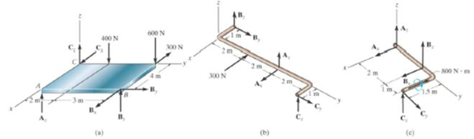
Prob. P5-3
Expert Solution & Answer
Want to see the full answer?
Check out a sample textbook solution
Students have asked these similar questions
You design a pin joint. The pin is made of a material with the yield strength of 325
MPa and ultimate strength of 500 MPa. The maximum allowed stress in service is
expressed as a tensor
0
100 0
σ
100
0
0 MPa
0
0
Evaluate the safety factor SF for stress in this design.
Write answer unitless rounding to 2 decimal places and enter decimals even if those
are zeros.
2. A single crystal of aluminum is oriented for a tensile test such that its slip plane normal makes an angle of 28.1° with the tensile axis. Three possible slip directions make angles of 62.4°, 72.0°, and 81.1° with the same tensile axis. (a) Which of these three slip directions is most favored? (b) If plastic deformation begins at a tensile stress of σ x = 1.95 MPa (280 psi), determine the critical resolved shear stress for aluminium. (c) If this single crystalspecimen is loaded under the new stress state: σ x =1.2 MPa σ y = -0.8 MPa, and τ xy = 0.6 MPa, howmuch is the resolve the shear stress along the most favored slip direction?
Please explain how to do each part and tell me if my drawing is correct. thank you
Chapter 5 Solutions
INTERNATIONAL EDITION---Engineering Mechanics: Statics, 14th edition (SI unit)
Ch. 5.2 - Draw the free-body diagram for the following...Ch. 5.2 - Draw the free-body diagram for the following...Ch. 5.2 - Draw the free-body diagram for the following...Ch. 5.2 - Draw the free-body diagram for the following...Ch. 5.2 - Draw the free-body diagram for the following...Ch. 5.2 - Draw the free-body diagram for the following...Ch. 5.2 - Draw the free-body diagram for the following...Ch. 5.2 - Draw the free-body diagram for the following...Ch. 5.2 - Draw the free-body diagram for the following...Ch. 5.4 - Draw the free body diagram of each object. Prob....
Ch. 5.4 - Determine the horizontal and vertical components...Ch. 5.4 - Determine the horizontal and vertical components...Ch. 5.4 - The truss is supported by a pin at A and a roller...Ch. 5.4 - Determine the components of reaction at the fixed...Ch. 5.4 - The 25 kg bar has a center of mass at G. If it is...Ch. 5.4 - Determine the reactions at the smooth contact...Ch. 5.4 - Determine the components of the support reactions...Ch. 5.4 - Determine the reactions at the supports. Prob....Ch. 5.4 - Determine the horizontal and vertical components...Ch. 5.4 - Determine the reactions at the supports. Prob....Ch. 5.4 - Determine the reactions at the supports. Prob....Ch. 5.4 - Determine the reactions at the supports. Prob....Ch. 5.4 - Determine the tension in the cable and the...Ch. 5.4 - The man attempts to a up port the toad of boards...Ch. 5.4 - Determine the components of reaction at the...Ch. 5.4 - The man has a weight W and stands at the center of...Ch. 5.4 - A uniform glass rod having a length L is placed in...Ch. 5.4 - The uniform rod AB has a mass of 40 kg. Determine...Ch. 5.4 - If the intensity of the distributed load acting on...Ch. 5.4 - If the roller at A and the pin at B can support a...Ch. 5.4 - The relay regulates voltage and current. Determine...Ch. 5.4 - Determine the reactions on the bent rod which is...Ch. 5.4 - The mobile crane is symmetrically supported by two...Ch. 5.4 - Determine the reactions acting on the smooth...Ch. 5.4 - A linear torsional spring deforms such that an...Ch. 5.4 - Determine the force P needed to pull the 50-kg...Ch. 5.4 - Determine the magnitude and direction of the...Ch. 5.4 - The operation of the fuel pump for an automobile...Ch. 5.4 - Determine the magnitude of force at the pin A and...Ch. 5.4 - The dimensions of a jib crane, which is...Ch. 5.4 - The dimensions of a jib crane, which is...Ch. 5.4 - The smooth pipe rests against the opening at the...Ch. 5.4 - The beam of negligible weight is supported...Ch. 5.4 - The cantilevered jib crane is used to support the...Ch. 5.4 - The cantilevered jib crane is used to support the...Ch. 5.4 - The bar of negligible weight is supported by two...Ch. 5.4 - Determine the stiffness k of each spring so that...Ch. 5.4 - The bulk head AD Is subjected to both water and...Ch. 5.4 - The boom supports the two vertical loads. Neglect...Ch. 5.4 - The boom is intended to support two vertical loads...Ch. 5.4 - The 10-kg uniform rod is pinned at end A. If It is...Ch. 5.4 - If the truck and its contents have a mass of 50 kg...Ch. 5.4 - Three uniform books each having a weight W and...Ch. 5.4 - Determine the reactions at the pin A and the...Ch. 5.4 - If rope BC will fail when the tension becomes 50...Ch. 5.4 - The rigid metal strip of negligible weight is used...Ch. 5.4 - The rigid metal strip of negligible weight is used...Ch. 5.4 - The cantilever footing is used to support a wail...Ch. 5.4 - The uniform beam has a weight Wand length l and is...Ch. 5.4 - A boy stands out at the end of the diving board,...Ch. 5.4 - The 30-N uniform rod has a length of l = 1 m. If s...Ch. 5.4 - The uniform rod has a length I and weight W. It is...Ch. 5.4 - I he uniform rod of length L and weight W is...Ch. 5.4 - Assuming that the foundation exerts a linearly...Ch. 5.4 - Assuming that the foundation exerts a linearly...Ch. 5.4 - If it is also subjected to a couple moment of 100...Ch. 5.4 - Determine the distance d for placement of the load...Ch. 5.4 - If d = 1 m, and = 30, determine me normal...Ch. 5.4 - The man attempts to pull the tour wheeler up the...Ch. 5.4 - Where is the best place to arrange most of the...Ch. 5.7 - Draw the free-body diagram of each object.Ch. 5.7 - In each case, write the moment equations about the...Ch. 5.7 - The uniform plate has a weight of 500 lb....Ch. 5.7 - Determine the reactions at the roller support A,...Ch. 5.7 - The rod is supported by smooth journal bearings at...Ch. 5.7 - Determine the support reactions at the smooth...Ch. 5.7 - Determine the force developed in the short link...Ch. 5.7 - Determine the components of reaction that the...Ch. 5.7 - Determine the tension each rope and the force that...Ch. 5.7 - If these components have weights WA = 45000 Wa =...Ch. 5.7 - Determine the components of reaction at the fixed...Ch. 5.7 - Determine the vertical reactions at the wheels C...Ch. 5.7 - Determine the components of reaction at A, the...Ch. 5.7 - Determine the tension in each of the three...Ch. 5.7 - Determine the components of reaction at hinges A...Ch. 5.7 - Determine me tension in each cable and the...Ch. 5.7 - The cables are attached to a smooth collar ring at...Ch. 5.7 - Determine the components of reaction at the...Ch. 5.7 - Determine the components of reaction at the...Ch. 5.7 - Determine the components of reaction at the...Ch. 5.7 - Determine the magnitude of F which will cause the...Ch. 5.7 - Determine the components of reaction at A and the...Ch. 5.7 - Determine the components of reaction at these...Ch. 5.7 - Determine the components or reaction at these...Ch. 5.7 - Compute the x, y, z components of reaction at the...Ch. 5.7 - Determine the magnitude of F2 which will cause the...Ch. 5.7 - At A the connection is with a ball-and-socket....Ch. 5.7 - If it is supported by a ball-and-socket joint at C...Ch. 5.7 - Determine the x, y, z components of reaction at...Ch. 5.7 - Determine the horizontal tension T in the belt on...Ch. 5.7 - Determine the horizontal tension T in the belt on...Ch. 5.7 - Determine the components of reaction at A and the...Ch. 5.7 - If the roller at 8 can sustain a maximum load of 3...Ch. 5.7 - Determine the reactions at the supports A and B...Ch. 5.7 - Determine the normal reaction at the roller A and...Ch. 5.7 - Determine the horizontal and vertical components...Ch. 5.7 - Determine the x, y, z components of reaction at...Ch. 5.7 - Determine the horizontal equilibrium force P that...Ch. 5.7 - Determine the x, y, z components of reaction at...Ch. 5.7 - Determine the x and z components of reaction at...
Knowledge Booster


Learn more about
Need a deep-dive on the concept behind this application? Look no further. Learn more about this topic, mechanical-engineering and related others by exploring similar questions and additional content below.Similar questions
- 4. Determine which of the following flow fields represent a possible incompressible flow? (a) u= x²+2y+z; v=x-2y+z;w= -2xy + y² + 2z a (b) V=U cose U coso 1 (9) [1-9] Usino |1 (4)] [+] V=-Usin 1+1arrow_forward3. Determine the flow rate through the pipe line show in the figure in ft³/s, and determine the pressures at A and C, in psi. 5' B C 12° 20' D 6"d 2nd- Water Aarrow_forward5. A flow is field given by V = x²₁³+xy, and determine 3 ·y³j- (a) Whether this is a one, two- or three-dimensional flow (b) Whether it is a possible incompressible flow (c) Determine the acceleration of a fluid particle at the location (X,Y,Z)=(1,2,3) (d) Whether the flow is rotational or irrotational flow?arrow_forward
- Solve this problem and show all of the workarrow_forwardSolve this problem and show all of the workarrow_forwarddraw the pneumatic circuit to operate a double-acting cylinder with: 1. Extension: Any of two manual conditions plus cylinder fully retracted, → Extension has both meter-in and meter-out, 2. Retraction: one manual conditions plus cylinder fully extended, → Retraction is very fast using quick exhaust valve.arrow_forward
- Correct answer is written below. Detailed and complete solution with fbd only. I will upvote, thank you. Expert solution plsarrow_forwardCorrect answer is written below. Detailed and complete solution with fbd only. I will upvote, thank you.arrow_forwardCorrect answer is written below. Detailed and complete solution with fbd only. I will upvote, thank you.arrow_forward
- Correct answer is written below. Detailed and complete solution only with fbd. I will upvote, thank you.arrow_forwardCorrect answer is written below. Detailed and complete solution only. I will upvote, thank you.arrow_forwardCorrect answer is written below. Detailed and complete solution with fbd only. I will upvote, thank you.arrow_forward
arrow_back_ios
SEE MORE QUESTIONS
arrow_forward_ios
Recommended textbooks for you
 Elements Of ElectromagneticsMechanical EngineeringISBN:9780190698614Author:Sadiku, Matthew N. O.Publisher:Oxford University Press
 Mechanics of Materials (10th Edition)Mechanical EngineeringISBN:9780134319650Author:Russell C. HibbelerPublisher:PEARSON
 Thermodynamics: An Engineering ApproachMechanical EngineeringISBN:9781259822674Author:Yunus A. Cengel Dr., Michael A. BolesPublisher:McGraw-Hill Education
 Control Systems EngineeringMechanical EngineeringISBN:9781118170519Author:Norman S. NisePublisher:WILEY
 Mechanics of Materials (MindTap Course List)Mechanical EngineeringISBN:9781337093347Author:Barry J. Goodno, James M. GerePublisher:Cengage Learning
 Engineering Mechanics: StaticsMechanical EngineeringISBN:9781118807330Author:James L. Meriam, L. G. Kraige, J. N. BoltonPublisher:WILEY
Elements Of Electromagnetics
Mechanical Engineering
ISBN:9780190698614
Author:Sadiku, Matthew N. O.
Publisher:Oxford University Press
Mechanics of Materials (10th Edition)
Mechanical Engineering
ISBN:9780134319650
Author:Russell C. Hibbeler
Publisher:PEARSON
Thermodynamics: An Engineering Approach
Mechanical Engineering
ISBN:9781259822674
Author:Yunus A. Cengel Dr., Michael A. Boles
Publisher:McGraw-Hill Education
Control Systems Engineering
Mechanical Engineering
ISBN:9781118170519
Author:Norman S. Nise
Publisher:WILEY
Mechanics of Materials (MindTap Course List)
Mechanical Engineering
ISBN:9781337093347
Author:Barry J. Goodno, James M. Gere
Publisher:Cengage Learning
Engineering Mechanics: Statics
Mechanical Engineering
ISBN:9781118807330
Author:James L. Meriam, L. G. Kraige, J. N. Bolton
Publisher:WILEY
Strain energy and strain energy density introduced; Author: Engineer4Free;https://www.youtube.com/watch?v=m14sqLGg4BQ;License: Standard youtube license