INTERNATIONAL EDITION---Engineering Mechanics: Statics, 14th edition (SI unit)
14th Edition
ISBN: 9780133918922
Author: Russell C. Hibbeler
Publisher: PEARSON
expand_more
expand_more
format_list_bulleted
Textbook Question
Chapter 5.4, Problem 28P
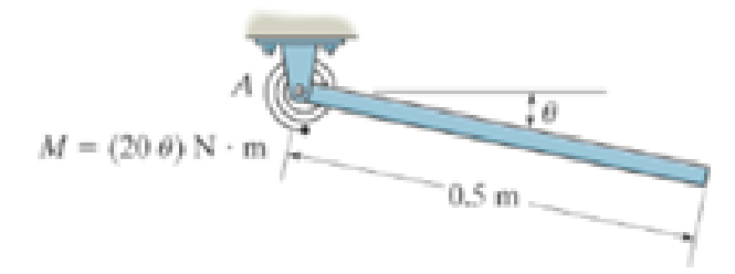
A linear torsional spring deforms such that an applied couple moment M is related to the spring’s rotation B in radians by the equation M = (20 θ) N · m. If such a spring is attached to the end of a pin-connected uniform 10-kg rod, determine the angle d for equilibrium. The spring is undeformed when θ = 0°.
Expert Solution & Answer
Learn your wayIncludes step-by-step video
schedule03:56
Students have asked these similar questions
Cart B , which weighs 75 kN, rolls along a sloping track that forms an angle B with the horizontal. The spring constant is 5 kN/m, and the spring is unstretched when x= 0. Determine the distance xcorresponding to equilibrium for the angle B indicated.Angle β= 60°
The weight of the uniform bar AB is W. The stiffness of the ideal spring attached to B is k and the spring is unstreched when theta= 80 degree.if W=kL the bar has three equilibrium position in the range of 0
Question 2:
The ideal spring of constant k-2.6 kN/m is attached to the disk at point A and the end fitting at point
B, as shown. The spring is unstretched when OA and Oв are both zero. If the disk is rotated 15° clockwise
and the end fitting is rotated 30°counterclockwise, determine the vector expression for the spring force
F.
Determine distance C so that the moment the spring force makes about the Z axis is equal to 10.82
N.m.
-
A = 15°1
A
250 mm
lllllll
900 mm k = 2.6 kN/m
OB = 30°
B
G
200 mm
Chapter 5 Solutions
INTERNATIONAL EDITION---Engineering Mechanics: Statics, 14th edition (SI unit)
Ch. 5.2 - Draw the free-body diagram for the following...Ch. 5.2 - Draw the free-body diagram for the following...Ch. 5.2 - Draw the free-body diagram for the following...Ch. 5.2 - Draw the free-body diagram for the following...Ch. 5.2 - Draw the free-body diagram for the following...Ch. 5.2 - Draw the free-body diagram for the following...Ch. 5.2 - Draw the free-body diagram for the following...Ch. 5.2 - Draw the free-body diagram for the following...Ch. 5.2 - Draw the free-body diagram for the following...Ch. 5.4 - Draw the free body diagram of each object. Prob....
Ch. 5.4 - Determine the horizontal and vertical components...Ch. 5.4 - Determine the horizontal and vertical components...Ch. 5.4 - The truss is supported by a pin at A and a roller...Ch. 5.4 - Determine the components of reaction at the fixed...Ch. 5.4 - The 25 kg bar has a center of mass at G. If it is...Ch. 5.4 - Determine the reactions at the smooth contact...Ch. 5.4 - Determine the components of the support reactions...Ch. 5.4 - Determine the reactions at the supports. Prob....Ch. 5.4 - Determine the horizontal and vertical components...Ch. 5.4 - Determine the reactions at the supports. Prob....Ch. 5.4 - Determine the reactions at the supports. Prob....Ch. 5.4 - Determine the reactions at the supports. Prob....Ch. 5.4 - Determine the tension in the cable and the...Ch. 5.4 - The man attempts to a up port the toad of boards...Ch. 5.4 - Determine the components of reaction at the...Ch. 5.4 - The man has a weight W and stands at the center of...Ch. 5.4 - A uniform glass rod having a length L is placed in...Ch. 5.4 - The uniform rod AB has a mass of 40 kg. Determine...Ch. 5.4 - If the intensity of the distributed load acting on...Ch. 5.4 - If the roller at A and the pin at B can support a...Ch. 5.4 - The relay regulates voltage and current. Determine...Ch. 5.4 - Determine the reactions on the bent rod which is...Ch. 5.4 - The mobile crane is symmetrically supported by two...Ch. 5.4 - Determine the reactions acting on the smooth...Ch. 5.4 - A linear torsional spring deforms such that an...Ch. 5.4 - Determine the force P needed to pull the 50-kg...Ch. 5.4 - Determine the magnitude and direction of the...Ch. 5.4 - The operation of the fuel pump for an automobile...Ch. 5.4 - Determine the magnitude of force at the pin A and...Ch. 5.4 - The dimensions of a jib crane, which is...Ch. 5.4 - The dimensions of a jib crane, which is...Ch. 5.4 - The smooth pipe rests against the opening at the...Ch. 5.4 - The beam of negligible weight is supported...Ch. 5.4 - The cantilevered jib crane is used to support the...Ch. 5.4 - The cantilevered jib crane is used to support the...Ch. 5.4 - The bar of negligible weight is supported by two...Ch. 5.4 - Determine the stiffness k of each spring so that...Ch. 5.4 - The bulk head AD Is subjected to both water and...Ch. 5.4 - The boom supports the two vertical loads. Neglect...Ch. 5.4 - The boom is intended to support two vertical loads...Ch. 5.4 - The 10-kg uniform rod is pinned at end A. If It is...Ch. 5.4 - If the truck and its contents have a mass of 50 kg...Ch. 5.4 - Three uniform books each having a weight W and...Ch. 5.4 - Determine the reactions at the pin A and the...Ch. 5.4 - If rope BC will fail when the tension becomes 50...Ch. 5.4 - The rigid metal strip of negligible weight is used...Ch. 5.4 - The rigid metal strip of negligible weight is used...Ch. 5.4 - The cantilever footing is used to support a wail...Ch. 5.4 - The uniform beam has a weight Wand length l and is...Ch. 5.4 - A boy stands out at the end of the diving board,...Ch. 5.4 - The 30-N uniform rod has a length of l = 1 m. If s...Ch. 5.4 - The uniform rod has a length I and weight W. It is...Ch. 5.4 - I he uniform rod of length L and weight W is...Ch. 5.4 - Assuming that the foundation exerts a linearly...Ch. 5.4 - Assuming that the foundation exerts a linearly...Ch. 5.4 - If it is also subjected to a couple moment of 100...Ch. 5.4 - Determine the distance d for placement of the load...Ch. 5.4 - If d = 1 m, and = 30, determine me normal...Ch. 5.4 - The man attempts to pull the tour wheeler up the...Ch. 5.4 - Where is the best place to arrange most of the...Ch. 5.7 - Draw the free-body diagram of each object.Ch. 5.7 - In each case, write the moment equations about the...Ch. 5.7 - The uniform plate has a weight of 500 lb....Ch. 5.7 - Determine the reactions at the roller support A,...Ch. 5.7 - The rod is supported by smooth journal bearings at...Ch. 5.7 - Determine the support reactions at the smooth...Ch. 5.7 - Determine the force developed in the short link...Ch. 5.7 - Determine the components of reaction that the...Ch. 5.7 - Determine the tension each rope and the force that...Ch. 5.7 - If these components have weights WA = 45000 Wa =...Ch. 5.7 - Determine the components of reaction at the fixed...Ch. 5.7 - Determine the vertical reactions at the wheels C...Ch. 5.7 - Determine the components of reaction at A, the...Ch. 5.7 - Determine the tension in each of the three...Ch. 5.7 - Determine the components of reaction at hinges A...Ch. 5.7 - Determine me tension in each cable and the...Ch. 5.7 - The cables are attached to a smooth collar ring at...Ch. 5.7 - Determine the components of reaction at the...Ch. 5.7 - Determine the components of reaction at the...Ch. 5.7 - Determine the components of reaction at the...Ch. 5.7 - Determine the magnitude of F which will cause the...Ch. 5.7 - Determine the components of reaction at A and the...Ch. 5.7 - Determine the components of reaction at these...Ch. 5.7 - Determine the components or reaction at these...Ch. 5.7 - Compute the x, y, z components of reaction at the...Ch. 5.7 - Determine the magnitude of F2 which will cause the...Ch. 5.7 - At A the connection is with a ball-and-socket....Ch. 5.7 - If it is supported by a ball-and-socket joint at C...Ch. 5.7 - Determine the x, y, z components of reaction at...Ch. 5.7 - Determine the horizontal tension T in the belt on...Ch. 5.7 - Determine the horizontal tension T in the belt on...Ch. 5.7 - Determine the components of reaction at A and the...Ch. 5.7 - If the roller at 8 can sustain a maximum load of 3...Ch. 5.7 - Determine the reactions at the supports A and B...Ch. 5.7 - Determine the normal reaction at the roller A and...Ch. 5.7 - Determine the horizontal and vertical components...Ch. 5.7 - Determine the x, y, z components of reaction at...Ch. 5.7 - Determine the horizontal equilibrium force P that...Ch. 5.7 - Determine the x, y, z components of reaction at...Ch. 5.7 - Determine the x and z components of reaction at...
Additional Engineering Textbook Solutions
Find more solutions based on key concepts
4.1 and 4.2 Sketch free-body diagram for the members shown.
Applied Statics and Strength of Materials (6th Edition)
Determine the maximum normal stress developed in the bar when it is subjected to a tension of P = 8kN.
Mechanics of Materials
1. In 2001 , the first iPodTM by Apple had a rated battery life of 10 hours (h) to run audio files. The 6th mod...
Thinking Like an Engineer: An Active Learning Approach (4th Edition)
Determine the angle between the two cables attached to the pipe.
Engineering Mechanics: Statics
What parts are included in the vehicle chassis?
Automotive Technology: Principles, Diagnosis, And Service (6th Edition) (halderman Automotive Series)
A particle travels 3long a straight line path y = 0.5x. If the x component of the particles velocity is vx = (2...
Engineering Mechanics: Dynamics (14th Edition)
Knowledge Booster
Learn more about
Need a deep-dive on the concept behind this application? Look no further. Learn more about this topic, mechanical-engineering and related others by exploring similar questions and additional content below.Similar questions
- A rigid rod is constrained between points A and B, as shown. A Spring CD has stiffness 1.5 N/mm and an unstretched length of 400mm. Assuming no friction between the collar and rod. Determine: a The weight of the collar W that produces the equilibrium configuration shown and, b The reaction between the collar and rod AB. X 400 mm B 600 mm C w Z A www 400 mm 400 mm 700 mm yarrow_forwardProblem 2. Consider the frame loaded as shown. If the reaction force at the roller at F is 250N, then find the force P applied for equilibrium. 0.2 m 0.2 m 0.3 m E 60° |A |B 0.6 m 0.3 marrow_forward1 ft 4 ft A 2 ft 45° X 5 B 3 ft Z 45° F₂ 5 ft 30° If F₁ = 300 lb. and F₂ is 250 lb., what are the reaction components on the smooth journal bearings A,B and C? Include a free body diagram of the bent pipe. F₁ lies entirely in the y-z plane.arrow_forward
- Q3 - The uniform bar OC of length L and mass ( m ) pivots freely about a horizontal axis through O. If the spring of modulus k is unstretched when C is coincident with A, determine the tension T required to hold the bar in the position shown. The diameter of the small pulley at D is negligible. T L/2 45° 30° B L/2 mg A wwwarrow_forwardFour forces are exerted on the eyebolt as shown in figure. If the net effect on the bolt is a direct pull of 1200 N in the y-direction, determine the necessary value of T if θ = 30° by considering the equilibrium condition in y-direction onlyarrow_forwardThree forces, FA, FB, and FC, intersect at the origin. Only 2 of these forces are shown on the diagram. Find the magnitude of FC and its direction coordinate angles for equilibrium, given:FA = 825 N, α = 150 °, β = 75 °FB = 600 N, θ = 20 °, Φ = 30 ° Answers The magnitude of FC is: FC = 798 N FC = 455 N FC = 331 N FC = 308 N FC = 522 N The direction coordinates angles of FC are: αC αC=69.1 ° αC=60.2 ° αC=40.7 ° αC=106 ° αC=43.8 ° βC βC=101 ° βC=262 ° βC=149 ° βC=171 ° βC=109 ° γC γC=65.3 ° γC=70.3 ° γC=111 ° γC=96.7 ° γC=1.70E2 °arrow_forward
- The bars shown are the same length. The spring is unstretched when alpha= 90°; the horizontal surface is smooth. For what value of a between 0 and 90° will the system remain in equilibrium?arrow_forwardIf F=1kN,the magnitude of the vertical reaction force developed at the point B?arrow_forwardCable AB passes over the small ideal pulley C without a change in its tension. What length of cable CD is required for static equilibrium in the position shown? What is the tension T in cable CD? 3' Answers: LCD = i TCD= i A 48° C B 59 lb ft lb Darrow_forward
- The ring at B is supported in equilibrium by spring AB, a cable running through the frictionless pulley at C, and cable BD. The pulley radius is 0.0267 m, and the unstretched length of spring AB is 0.24 m. If F1 = 340 N and F2 = 200 N at 0 = 50 degrees, determine the spring constant k and the force exerted on the ring by cable BD expressed in Cartesian components. F1 C В www d k A F2 D Values for dimensions on the figure are given in the following table. Note the figure may not be to scale. Variable Value a 0.400 m 0.160 m 0.267 m d. 0.107 m Note the figure may not be to scale. k = N/m F BD = ) Narrow_forwardCable AB passes over the small ideal pulley C with- out a change in its tension. What length of cable CD is required for static equilibrium in the position shown? What is the tension T in cable CD? 4 A 45° 2' B 50 lb 17/17arrow_forwardThe 0.6 m uniform slender bar has a mass of 5 kg. Two springs 1 and 2 having stiffness k, = 80 N/m and k₂= 45 N/m respectively are attached at end B of the slender bar. A 20 kg mass is suspended through a rope of negligible weight at the other end as shown. If a counter-clockwise moment M = 10 N. m is applied on the bar when it is at rest in the horizontal position, determine the angular velocity (₂) of the slender bar when it has rotated 30° couterclockwise. Note: Both springs always remain vertical because of the roller supports shown and are unstretched when the bar is horizontal. (Include any diagrams needed to support your solutions) 201 0 10 Km 04M A-80 N/m 45 N/m O 06marrow_forward
arrow_back_ios
SEE MORE QUESTIONS
arrow_forward_ios
Recommended textbooks for you
- International Edition---engineering Mechanics: St...Mechanical EngineeringISBN:9781305501607Author:Andrew Pytel And Jaan KiusalaasPublisher:CENGAGE L
International Edition---engineering Mechanics: St...
Mechanical Engineering
ISBN:9781305501607
Author:Andrew Pytel And Jaan Kiusalaas
Publisher:CENGAGE L
Mechanical SPRING DESIGN Strategy and Restrictions in Under 15 Minutes!; Author: Less Boring Lectures;https://www.youtube.com/watch?v=dsWQrzfQt3s;License: Standard Youtube License