
Videos
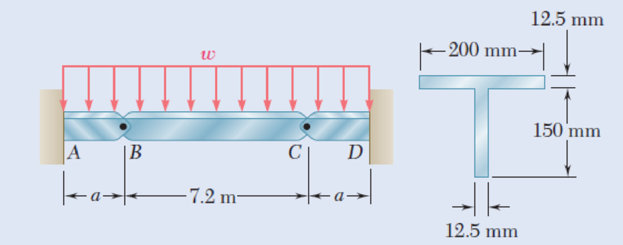
Beams AB, BC, and CD have the cross section shown and are pin-connected at B and C. Knowing that the allowable normal stress is +110 MPa in tension and –150 MPa in compression, determine (a) the largest permissible value of w if beam BC is not to be overstressed, (b) the corresponding maximum distance a for which the cantilever beams AB and CD are not overstressed.
Fig. P5.89
(a)
The largest permissible value of w for the condition that the beam BC is not overstressed.
Answer to Problem 89P
The largest permissible value of w is
Explanation of Solution
Given information:
The allowable normal stress of the material in tension is
The allowable normal stress of the material in compression is
Calculation:
Show the free-body diagram of the section BC as in Figure 1.
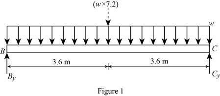
Determine the vertical reaction at point C by taking moment about point B.
Determine the vertical reaction at point B by resolving the vertical component of forces.
Show the free-body diagram of the section AB as in Figure 2.

Determine the vertical reaction at point A by resolving the vertical component of forces.
Determine the moment at point A by taking moment about the point A.
Show the free-body diagram of the section CD as in Figure 3.
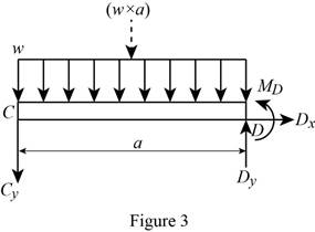
Determine the vertical reaction at point D by resolving the vertical component of forces.
Determine the moment at point D by taking moment about the point D.
Shear force:
Show the calculation of shear force as follows;
Show the calculated shear force values as in Table 1.
| Location (x) m | Shear force (V) kN |
| A | |
| B | 3.6w |
| C | –3.6w |
| D |
Plot the shear force diagram as in Figure 4.
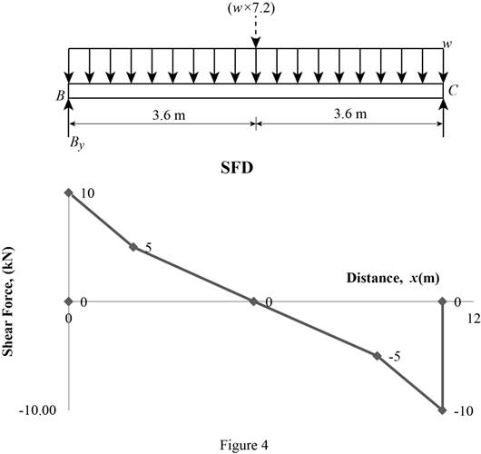
Location of the maximum bending moment:
The maximum bending moment occurs where the shear force changes sign.
Refer to Figure 4;
Use the similar triangle concept.
The maximum bending moment occurs at a distance of
Bending moment:
Show the calculation of the bending moment as follows;
Show the calculated bending moment values as in Table 2.
| Location (x) m | Bending moment (M) kN-m |
| A | |
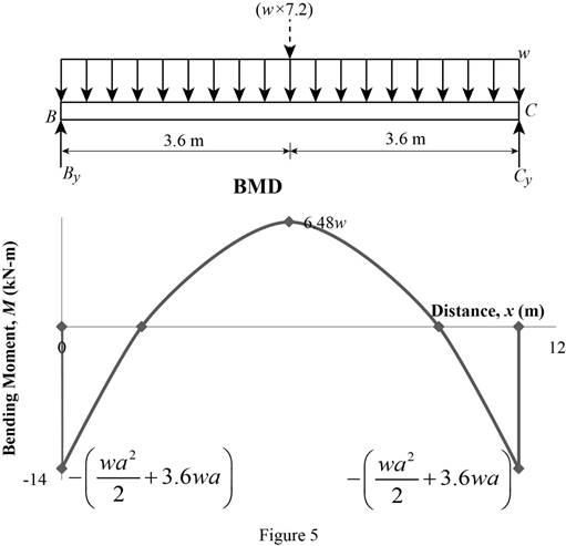
| B | 0 |
| Max BM | 6.48w |
| C | 0 |
| D |
Plot the bending moment diagram as in Figure 5.
Show the free-body diagram of the T-section as in Figure 6.
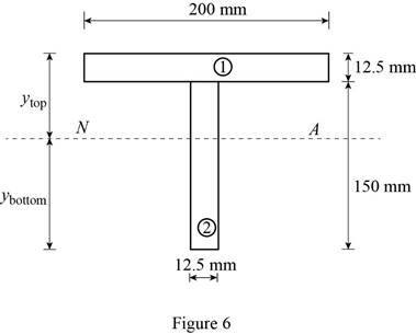
Determine the centroid in y-axis
Here, the area of the section 1 is
Refer to Figure 4;
Substitute
Determine the moment of inertia (I) using the equation.
Here, the depth of the section 1 is
Substitute 12.5 mm for
Refer to Figure 4;
Tension at Points B and D:
Refer to Figure 5;
Determine the moment at points B and D using the relation.
Substitute 110 MPa for
Compression at Points B and C:
Refer to Figure 5;
Determine the moment at points B and D using the relation.
Substitute –150 MPa for
Tension at maximum bending moment:
Refer to Figure 5;
Determine the maximum moment using the relation.
Substitute 110 MPa for
Compression at maximum bending moment:
Refer to Figure 5;
Determine the maximum moment using the relation.
Substitute –150 MPa for
Refer to the calculated distribution loads; the smallest value controls the design.
Refer to Figure 5;
Equate the maximum bending moment calculated and the maximum bending moment in the tension side.
Therefore, the largest permissible value of w for the condition that the beam BC is not overstressed is
(b)
The maximum distance a for the condition that the beams AB and CD are not overstressed.
Answer to Problem 89P
The maximum distance a for the condition that the beams AB and CD are not overstressed is
Explanation of Solution
Refer to Part (a), Figure 4;
The maximum bending moment in the beams AB and CD occurs at the ends A and D.
The calculated maximum bending moment at the points A and D is as follows:
The maximum allowable compression moment at the points A and D is as follows:
Equate the values;
Refer to the answer of the part (a);
Substitute
Therefore, the maximum distance a for the condition that the beams AB and CD are not overstressed is
Want to see more full solutions like this?
Chapter 5 Solutions
EBK MECHANICS OF MATERIALS


- Need help, please show all work, steps, units and please box out and round answers to 3 significant figures. Thank you!..arrow_forwardNeed help, please show all work, steps, units and please box out and round answers to 3 significant figures. Thank you!...arrow_forwardFL y b C Z Determine the moment about O due to the force F shown, the magnitude of the force F = 76.0 lbs. Note: Pay attention to the axis. Values for dimensions on the figure are given in the following table. Note the figure may not be to scale. Variable Value a 1.90 ft b 2.80 ft с 2.60 ft d 2.30 ft Mo 144 ft-lb = -212 × 1 + xk) ☑+212arrow_forward
- 20 in. PROBLEM 15.206 Rod AB is connected by ball-and-socket joints to collar A and to the 16-in.-diameter disk C. Knowing that disk C rotates counterclockwise at the constant rate ₁ =3 rad/s in the zx plane, determine the velocity of collar A for the position shown. 25 in. B 8 in. Answer: -30 in/s =arrow_forwardB Z 001 2.5 ft PROBLEM 15.236 The arm AB of length 16 ft is used to provide an elevated platform for construction workers. In the position shown, arm AB is being raised at the constant rate de/dt = 0.25 rad/s; simultaneously, the unit is being rotated about the Y axis at the constant rate ₁ =0.15 rad/s. Knowing that 20°, determine the velocity and acceleration of Point B. Answers: 1.371 +3.76)+1.88k ft/s a=1.22 -0.342)-0.410k ft/s² Xarrow_forwardF1 3 5 4 P F2 F2 Ꮎ Ꮎ b P 3 4 5 F1 The electric pole is subject to the forces shown. Force F1 245 N and force F2 = 310 N with an angle = 20.2°. Determine the moment about point P of all forces. Take counterclockwise moments to be positive. = Values for dimensions on the figure are given in the following table. Note the figure may not be to scale. Variable Value a 2.50 m b 11.3 m C 13.0 m The moment about point P is 3,414 m. × N- If the moment about point P sums up to be zero. Determine the distance c while all other values remained the same. 1.26 m.arrow_forward
- Z 0.2 m B PROBLEM 15.224 Rod AB is welded to the 0.3-m-radius plate, which rotates at the constant rate ₁ = 6 rad/s. Knowing that collar D moves toward end B of the rod at a constant speed u = 1.3 m, determine, for the position shown, (a) the velocity of D, (b) the acceleration of D. Answers: 1.2 +0.5-1.2k m/s a=-7.21-14.4k m/s² A 0.25 m 0.3 marrow_forwardI am trying to code in MATLAB the equations of motion for malankovich orbitlal elements. But, I am having a problem with the B matrix. Since f matrix is 7x1 and a_d matrix has to be 3x1, the B matrix has to be 7x3. I don't know how that is possible. Can you break down the B matrix for me and let me know what size it is?arrow_forwardI am trying to code the solution to the problem in the image in MATLAB. I wanted to know what is the milankovich constraint equation that is talked about in part b.arrow_forward
- mylabmastering.pearson.com Chapter 12 - Lecture Notes.pptx: (MAE 272-01) (SP25) DY... P Pearson MyLab and Mastering Scoresarrow_forwardAir modeled as an ideal gas enters an insulated compressor at a temperature of 300 K and 100 kPa, and leaves at 600 kPa. The mass flowrate of air entering the compressor is 50 kg/hr, and the power consumed by the compressor is 3 kW. (Rair = 0.287 kJ/kg-K, k = 1.4, cp = 1.0045 kJ/kg-K, cv = 0.718 kJ/kg-K) Determine the isentropic exit temperature (Te,s) of the air in [K]. Determine the actual exit temperature (Te) of the air in [K]. Determine the isentropic efficiency of the compressor. (Answer: ηc,s = 93.3%) Determine the rate of entropy generated through the compressor in [kW/K]. (Answer: Ṡgen = 0.000397 kW/K)arrow_forwardmylabmastering.pearson.com Chapter 12 - Lecture Notes.pptx: (MAE 272-01) (SP25) DY... P Pearson MyLab and Mastering Scoresarrow_forwardarrow_back_iosSEE MORE QUESTIONSarrow_forward_ios
 Elements Of ElectromagneticsMechanical EngineeringISBN:9780190698614Author:Sadiku, Matthew N. O.Publisher:Oxford University Press
 Mechanics of Materials (10th Edition)Mechanical EngineeringISBN:9780134319650Author:Russell C. HibbelerPublisher:PEARSON
 Thermodynamics: An Engineering ApproachMechanical EngineeringISBN:9781259822674Author:Yunus A. Cengel Dr., Michael A. BolesPublisher:McGraw-Hill Education
 Control Systems EngineeringMechanical EngineeringISBN:9781118170519Author:Norman S. NisePublisher:WILEY
 Mechanics of Materials (MindTap Course List)Mechanical EngineeringISBN:9781337093347Author:Barry J. Goodno, James M. GerePublisher:Cengage Learning
 Engineering Mechanics: StaticsMechanical EngineeringISBN:9781118807330Author:James L. Meriam, L. G. Kraige, J. N. BoltonPublisher:WILEY