
Concept explainers
Videos
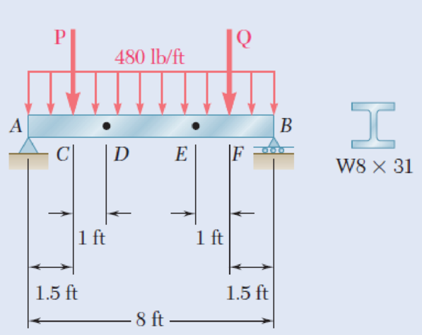
The beam AB supports a uniformly distributed load of 480 lb/ft and two concentrated loads P and Q. The normal stress due to bending on the bottom edge of the lower flange is +14.85 ksi at D and +10.65 ksi at E. (a) Draw the shear and bending-moment diagrams for the beam. (b) Determine the maximum normal stress due to bending that occurs in the beam.
Fig. P5.63
(a)
Draw the shear and bending-moment diagrams for the beam.
Explanation of Solution
Given information:
The normal stress due to bending at the point D is
The normal stress due to bending at the point E is
Refer to Appendix C “Properties of Rolled-Steel Sections” in the textbook.
The section modulus (S) for
Determine the bending moment at point D
Here, the normal stress at point D is
Substitute 14.85 ksi for
Determine the bending moment at point E
Here, the normal stress at point E is
Substitute 10.65 ksi for
Show the free-body diagram of the region DE as in Figure 1.
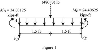
Determine the vertical reaction at point D by taking moment about point E.
Show the free body diagram of the region ACD as in Figure 2.
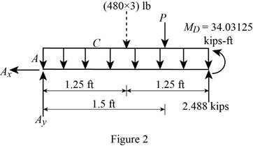
Determine the magnitude of the load P by taking moment about the point A.
Determine the vertical reaction at point A by resolving the vertical component of forces.
Show the free body diagram of the entire beam as in Figure 3.
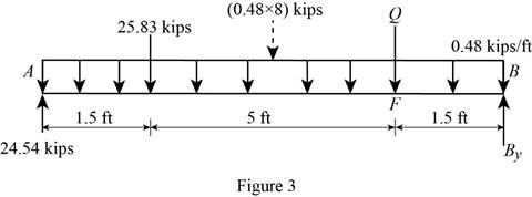
Determine the magnitude of the load P by taking moment about the point B.
Determine the vertical reaction at point A by resolving the vertical component of forces.
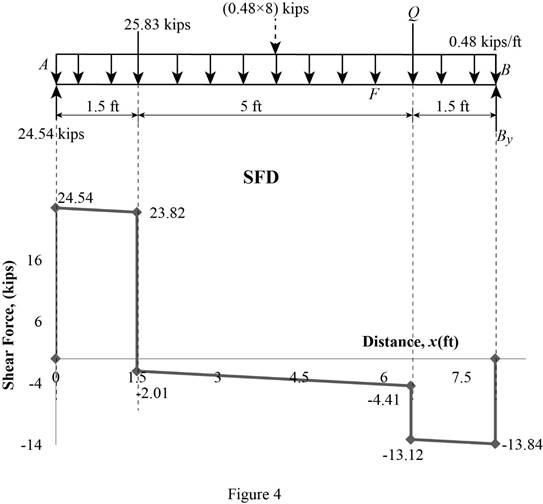
Shear force:
Show the calculation of shear force as follows;
Show the calculated shear force values as in Table 1.
| Location (x) ft | Shear force (V) kips |
| A | 24.54 |
| C (Left) | 23.82 |
| C (Right) | –2.01 |
| F (Left) | –4.41 |
| F (Right) | –13.12 |
| B | –13.84 |
Plot the shear force diagram as in Figure 4.
Bending moment:
Show the calculation of the bending moment as follows;
Show the calculated bending moment values as in Table 2.
| Location (x) ft | Bending moment (M) kips-ft |
| A | 0 |
| C | 36.27 |
| F | 19.77 |
| B | 0 |
Plot the bending moment diagram as in Figure 5.
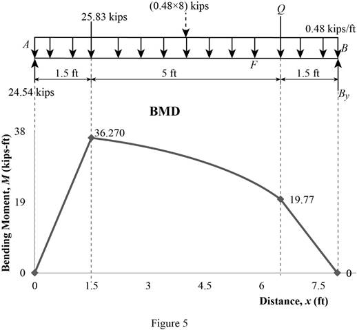
Refer to Figure 5;
The maximum absolute bending moment is
(b)
The maximum normal stress due to bending.
Answer to Problem 63P
The maximum normal stress due to bending is
Explanation of Solution
Given information:
Refer to Appendix C “Properties of Rolled-Steel Sections” in the textbook.
The section modulus (S) for
The maximum absolute bending moment is
Determine the maximum normal stress
Substitute
Therefore, the maximum normal stress due to bending is
Want to see more full solutions like this?
Chapter 5 Solutions
EBK MECHANICS OF MATERIALS


- Q5:(? Design the duct system of the figure below by using the balanced pressure method. The velocity in the duct attached to the AHU must not exceed 5m/s. The pressure loss for each diffuser is equal to 10Pa. 100CFM 100CFM 100CFM ☑ ☑ 40m AHU -16m- 8m- -12m- 57m 250CFM 40m -14m- 26m 36m ☑ 250CFMarrow_forwardA mass of ideal gas in a closed piston-cylinder system expands from 427 °C and 16 bar following the process law, pv1.36 = Constant (p times v to the power of 1.36 equals to a constant). For the gas, initial : final pressure ratio is 4:1 and the initial gas volume is 0.14 m³. The specific heat of the gas at constant pressure, Cp = 0.987 kJ/kg-K and the specific gas constant, R = 0.267 kJ/kg.K. Determine the change in total internal energy in the gas during the expansion. Enter your numerical answer in the answer box below in KILO JOULES (not in Joules) but do not enter the units. (There is no expected number of decimal points or significant figures).arrow_forwardmy ID# 016948724. Please solve this problem step by steparrow_forward
- My ID# 016948724 please find the forces for Fx=0: fy=0: fz=0: please help me to solve this problem step by steparrow_forwardMy ID# 016948724 please solve the proble step by step find the forces fx=o: fy=0; fz=0; and find shear moment and the bending moment diagran please draw the diagram for the shear and bending momentarrow_forwardMy ID#016948724. Please help me to find the moment of inertia lx ly are a please show to solve step by stepsarrow_forward
- My ID# 016948724arrow_forwardPlease do not use any AI tools to solve this question. I need a fully manual, step-by-step solution with clear explanations, as if it were done by a human tutor. No AI-generated responses, please.arrow_forwardPlease do not use any AI tools to solve this question. I need a fully manual, step-by-step solution with clear explanations, as if it were done by a human tutor. No AI-generated responses, please.arrow_forward
 International Edition---engineering Mechanics: St...Mechanical EngineeringISBN:9781305501607Author:Andrew Pytel And Jaan KiusalaasPublisher:CENGAGE L
 Principles of Heat Transfer (Activate Learning wi...Mechanical EngineeringISBN:9781305387102Author:Kreith, Frank; Manglik, Raj M.Publisher:Cengage Learning
 Mechanics of Materials (MindTap Course List)Mechanical EngineeringISBN:9781337093347Author:Barry J. Goodno, James M. GerePublisher:Cengage Learning