
Concept explainers
Videos
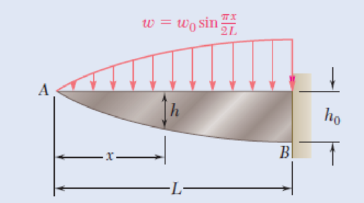
5.128 and 5.129 The beam AB, consisting of a cast-iron plate of uniform thickness b and length L, is to support the distributed load w(x) shown. (a) Knowing that the beam is to be of constant strength, express h in terms of x, L, and h0. (b) Determine the smallest value of h0 if L = 750 mm, b = 30 mm, w0 = 300 kN/m, and σall = 200 MPa.
Fig. P5.129
(a)
Express h in terms of x, L, and
Answer to Problem 129P
The expression for h in terms of x, L, and
Explanation of Solution
Given information:
The uniform thickness of the beam is b.
The length of the beam is L.
The rise of the beam is
Calculation:
By definition;
Substitute
Integrate the equation to find V.
Apply the boundary condition;
Substitute 0 for V and 0 for x in Equation (1).
Substitute
By definition;
Substitute
Apply the boundary condition;
Substitute 0 for M and 0 for x in Equation (2).
Substitute 0 for
Determine the section modulus (S) of the beam using the relation.
Here, the allowable stress in the beam is
Substitute
Determine the section modulus (S) of the rectangular cross section using the relation.
Here, the width of the beam is b and the depth of the beam is h.
Substitute
When
Substitute
Substitute
Therefore, the expression for h in terms of x, L, and
(b)
The smallest value of
Answer to Problem 129P
The smallest value of
Explanation of Solution
Given information:
The maximum allowable stress is
The length of the beam is
The distributed load is
The width of the beam is
Calculation:
Substitute
Therefore, the smallest value of
Want to see more full solutions like this?
Chapter 5 Solutions
EBK MECHANICS OF MATERIALS


- Part A The man pulls on the rope with a force of F = 30 N as shown in (Figure 1). Figure 1.5 m 3 m. 4m 10.5 m 1 of 1 Determine the position vector from O to A. Express the x, y, and z components of the position vector in meters to three significant figures separated by commas. ΜΕ ΑΣΦ vec (TOA). (TOA)y. (TOA)== Submit Request Answer Part B m Determine the position vector from O to B. Express the x, y, and z components of the position vector in meters to three significant figures separated by commas. ΜΕ ΑΣΦ ↓↑ vec (TOB)x, (TOB)y, (TOB) = Submit Request Answer Part C Complete previous part(s) Provide Feedback ? marrow_forward4 Part A The tool is used to shut off gas valves that are difficult to access (Figure 1). Figure 0.25 m 30 0,4 m < 1 of 1 If the force F= {-60i+40j+15k} N is applied to the handle, determine the component of the moment created about the z axis of the valve. Express your answer with the appropriate units. Mz = Value Submit Request Answer Provide Feedback | ? Unitsarrow_forward3. A steam power plant has an average monthly net power delivery of 740 MW over the course of a year. This power delivery is accomplished by burning coal in the boiler. The coal has a heating value of 9150 Btu/lbm. The cost of the coal is $14.20/ton. The overall thermal efficiency of the plant is, nth Wnet Qboiler 0.26 = 26% Determine the annual cost of the coal required to deliver the given average monthly power.arrow_forward
- The cable exerts a force of P = 4 kN at the end of the 8-m-long crane boom. A P 8 m B -x- I'm En ▾ Part A If 0 = 30°, determine the placement x of the boom at B so that this force creates a maximum moment about point O. Express your answer to three significant figures and include the appropriate units. x = 9.81 m Submit Previous Answers ✓ Correct ▾ Part B What is this moment? Express your answer to three significant figures and include the appropriate units. Assume the positive direction is counterclockwise. (Mo) max 43.7 = E ? N Submit Previous Answers Request Answer X Incorrect; Try Again; 28 attempts remaining Enter your answer with a different unit type. Review a list of acceptable units.arrow_forwardFind highest and lowest temperature.arrow_forwardExplained step by step.arrow_forward
- The bevel gear shown in is subjected to the force F which is caused from contact with another gear. Part A F (201+8j 15k) N 40 mm Determine the moment of this force about the y axis of the gear shaft. Express your answer with the appropriate units. My = Value Submit Request Answer ? Units 30 mmarrow_forwardConsider the beam in. Part A 1.5 ft 200 lb 200lb 2 ft 30° 1.25 ft 30° If F 90 lb, determine the resultant couple moment. = Express your answer in pound-feet to three significant figures. Assume the positive direction is counterclockwise. ΑΣΦ vec MR = Submit Request Answer ? lb.ftarrow_forward4. An operating parameter often used by power plant engineers is the heat rate. The heat rate is defined as, HR Qbioler Wnet where Qbioler is the heat transfer rate (Btu/h) to the water in the boiler due to the combustion of a fuel and Wnet is the net power (kW) delivered by the plant. In comparison, the thermal efficiency of the power plant is defined as, nth Wnet Qbioler where the numerator and denominator have the same units. Consider a power plant that is delivering 1000 MW of power while utilizing a heat transfer rate of 3570 MW at the boiler. Determine the heat rate and thermal efficiency of this power plant.arrow_forward
 Elements Of ElectromagneticsMechanical EngineeringISBN:9780190698614Author:Sadiku, Matthew N. O.Publisher:Oxford University Press
 Mechanics of Materials (10th Edition)Mechanical EngineeringISBN:9780134319650Author:Russell C. HibbelerPublisher:PEARSON
 Thermodynamics: An Engineering ApproachMechanical EngineeringISBN:9781259822674Author:Yunus A. Cengel Dr., Michael A. BolesPublisher:McGraw-Hill Education
 Control Systems EngineeringMechanical EngineeringISBN:9781118170519Author:Norman S. NisePublisher:WILEY
 Mechanics of Materials (MindTap Course List)Mechanical EngineeringISBN:9781337093347Author:Barry J. Goodno, James M. GerePublisher:Cengage Learning
 Engineering Mechanics: StaticsMechanical EngineeringISBN:9781118807330Author:James L. Meriam, L. G. Kraige, J. N. BoltonPublisher:WILEY