
Vector Mechanics for Engineers: Statics and Dynamics
12th Edition
ISBN: 9781259638091
Author: Ferdinand P. Beer, E. Russell Johnston Jr., David Mazurek, Phillip J. Cornwell, Brian Self
Publisher: McGraw-Hill Education
expand_more
expand_more
format_list_bulleted
Concept explainers
Videos
Textbook Question
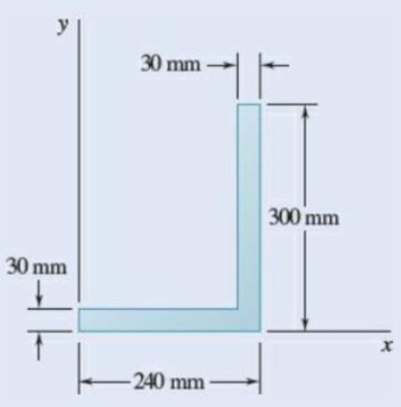
Chapter 5.2, Problem 5.52P
Determine the volume and the surface area of the solid obtained by rotating the area of Prob. 5.1 about (a) the line x = 240 mm, (b) the y axis.
Fig. P5.1
Expert Solution & Answer
Want to see the full answer?
Check out a sample textbook solution
Students have asked these similar questions
Question 5
Calculate the Moment about the point B in
Nx m
B
500 N
A
2 m
1.2 m
0.8 m
300 N
7
Please help
Question 3
Calculate the Moment about the point B in
Nxm
A
300 N
2 m
500 N
4
B
с
0.8 m
1.2 m
Chapter 5 Solutions
Vector Mechanics for Engineers: Statics and Dynamics
Ch. 5.1 - 5.1 through 5.9 Locate the centroid of the plane...Ch. 5.1 - Locate the centroid of the plane area shown.Ch. 5.1 - Locate the centroid of the plane area shown.Ch. 5.1 - Locate the centroid of the plane area shown.Ch. 5.1 - Locate the centroid of the plane area shown.Ch. 5.1 - Locate the centroid of the plane area shown.Ch. 5.1 - Locate the centroid of the plane area shown.Ch. 5.1 - Locate the centroid of the plane area shown.Ch. 5.1 - Locate the centroid of the plane area shown.Ch. 5.1 - Locate the centroid of the plane area shown.
Ch. 5.1 - Locate the centroid of the plane area shown.Ch. 5.1 - Locate the centroid of the plane area shown.Ch. 5.1 - Locate the centroid of the plane area shown.Ch. 5.1 - Locate the centroid of the plane area shown.Ch. 5.1 - Locate the centroid of the plane area shown.Ch. 5.1 - PROBLEM 5.16 Determine the y coordinate of the...Ch. 5.1 - Show that as r1 approaches r2, the location of the...Ch. 5.1 - Prob. 5.18PCh. 5.1 - Prob. 5.19PCh. 5.1 - A built-up beam is constructed by nailing seven...Ch. 5.1 - The horizontal x axis is drawn through the...Ch. 5.1 - The horizontal x-axis is drawn through the...Ch. 5.1 - PROBLEM 5.23 The first moment of the shaded area...Ch. 5.1 - A thin, homogeneous wire is bent to form the...Ch. 5.1 - A thin, homogeneous wire is bent to form the...Ch. 5.1 - Prob. 5.26PCh. 5.1 - A thin, homogeneous wire is bent to form the...Ch. 5.1 - Prob. 5.28PCh. 5.1 - The frame for a sign is fabricated from thin, flat...Ch. 5.1 - The homogeneous wire ABCD is bent as shown and is...Ch. 5.1 - The homogeneous wire ABCD is bent as shown and is...Ch. 5.1 - Prob. 5.32PCh. 5.1 - Knowing that the distance h has been selected to...Ch. 5.2 - Determine by direct integration the centroid of...Ch. 5.2 - 5.34 through 5.36 Determine by direct integration...Ch. 5.2 - 5.34 through 5.36 Determine by direct integration...Ch. 5.2 - 5.37 through 5.39 Determine by direct integration...Ch. 5.2 - 5.37 through 5.39 Determine by direct integration...Ch. 5.2 - Prob. 5.39PCh. 5.2 - 5.40 and 5.41 Determine by direct integration the...Ch. 5.2 - 5.40 and 5.41 Determine by direct integration the...Ch. 5.2 - 5.42 Determine by direct integration the centroid...Ch. 5.2 - 5.43 and 5.44 Determine by direct integration the...Ch. 5.2 - 5.43 and 5.44 Determine by direct integration the...Ch. 5.2 - 5.45 and 5.46 A homogeneous wire is bent into the...Ch. 5.2 - 5.45 and 5.46 A homogeneous wire is bent into the...Ch. 5.2 - A homogeneous wire is bent into the shape shown....Ch. 5.2 - 5.48 and 5.49 Determine by direct integration the...Ch. 5.2 - Prob. 5.49PCh. 5.2 - Prob. 5.50PCh. 5.2 - Determine the centroid of the area shown when a =...Ch. 5.2 - Determine the volume and the surface area of the...Ch. 5.2 - Determine the volume and the surface area of the...Ch. 5.2 - Determine the volume and the surface area of the...Ch. 5.2 - Determine the volume and the surface area of the...Ch. 5.2 - Determine the volume of the solid generated by...Ch. 5.2 - Prob. 5.57PCh. 5.2 - Prob. 5.58PCh. 5.2 - Prob. 5.59PCh. 5.2 - Determine the capacity, in liters, of the punch...Ch. 5.2 - Determine the volume and total surface area of the...Ch. 5.2 - Prob. 5.62PCh. 5.2 - Determine the total surface area of the solid...Ch. 5.2 - Determine the volume of the brass collar obtained...Ch. 5.2 - The shade for a wall-mounted light is formed from...Ch. 5.3 - 5.66 and 5.67 For the beam and loading shown,...Ch. 5.3 - 5.66 and 5.67 For the beam and loading shown,...Ch. 5.3 - 5.68 through 5.73 Determine the reactions at the...Ch. 5.3 - 5.68 through Determine the reactions at the beam...Ch. 5.3 - 5.68 through 5.73 Determine the reactions at the...Ch. 5.3 - 5.68 through Determine the reactions at the beam...Ch. 5.3 - 5.68 through 5.73 Determine the reactions at the...Ch. 5.3 - 5.68 through 5.73 Determine the reactions at the...Ch. 5.3 - Determine (a) the distance a so that the vertical...Ch. 5.3 - Prob. 5.75PCh. 5.3 - Determine the reactions at the beam supports for...Ch. 5.3 - Determine (a) the distributed load w0 at the end D...Ch. 5.3 - The beam AB supports two concentrated loads and...Ch. 5.3 - For the beam and loading of Prob. 5.78, determine...Ch. 5.3 - The cross section of a concrete dam is as shown....Ch. 5.3 - Prob. 5.81PCh. 5.3 - The dam for a lake is designed to withstand the...Ch. 5.3 - Prob. 5.83PCh. 5.3 - The friction force between a 6 6-ft square sluice...Ch. 5.3 - A freshwater marsh is drained to the ocean through...Ch. 5.3 - Prob. 5.86PCh. 5.3 - The 3 4-m side of an open tank is hinged at its...Ch. 5.3 - Prob. 5.88PCh. 5.3 - A 0.5 0.8-m gate AB is located at the bottom of a...Ch. 5.3 - Prob. 5.90PCh. 5.3 - Prob. 5.91PCh. 5.3 - Prob. 5.92PCh. 5.3 - Prob. 5.93PCh. 5.3 - Prob. 5.94PCh. 5.3 - The square gate AB is held in the position shown...Ch. 5.4 - Consider the composite body shown. Determine (a)...Ch. 5.4 - A cone and a cylinder of the same radius a and...Ch. 5.4 - Determine the location of the center of gravity of...Ch. 5.4 - Prob. 5.99PCh. 5.4 - For the stop bracket shown, locate the x...Ch. 5.4 - Fig. P5.100 and P5.101 5.101 For the stop bracket...Ch. 5.4 - For the machine element shown, locate the x...Ch. 5.4 - Fig. P5.102 and P5.103 5.103 For the machine...Ch. 5.4 - For the machine element shown, locate the y...Ch. 5.4 - For the machine element shown, locate the x...Ch. 5.4 - 5.106 and 5.107 Locate the center of gravity of...Ch. 5.4 - 5.106 and 5.107 Locate the center of gravity of...Ch. 5.4 - A corner reflector for tracking by radar has two...Ch. 5.4 - A wastebasket, designed to fit in the corner of a...Ch. 5.4 - Prob. 5.110PCh. 5.4 - Prob. 5.111PCh. 5.4 - Prob. 5.112PCh. 5.4 - Locate the center of gravity of the sheet-metal...Ch. 5.4 - A thin steel wire with a uniform cross section is...Ch. 5.4 - The frame of a greenhouse is constructed from...Ch. 5.4 - Locate the center of gravity of the figure shown,...Ch. 5.4 - PROBLEM 5.117 Locate the center of gravity of the...Ch. 5.4 - A scratch awl has a plastic handle and a steel...Ch. 5.4 - Prob. 5.119PCh. 5.4 - PROBLEM 5.120 A brass collar, of length 2.5 in.,...Ch. 5.4 - Prob. 5.121PCh. 5.4 - Prob. 5.122PCh. 5.4 - Prob. 5.123PCh. 5.4 - Prob. 5.124PCh. 5.4 - PROBLEM 5.125 Locate the centroid of the volume...Ch. 5.4 - PROBLEM 5.126 Locate the centroid of the volume...Ch. 5.4 - Prob. 5.127PCh. 5.4 - Prob. 5.128PCh. 5.4 - PROBLEM 5.129 Locate the centroid of the volume...Ch. 5.4 - Prob. 5.130PCh. 5.4 - Prob. 5.131PCh. 5.4 - PROBLEM 5.132 The sides and the base of a punch...Ch. 5.4 - Locate the centroid of the section shown, which...Ch. 5.4 - Prob. 5.134PCh. 5.4 - Prob. 5.135PCh. 5.4 - Alter grading a lot, a builder places four stakes...Ch. 5 - 5.137 and 5.138 Locate the centroid of the plane...Ch. 5 - 5.137 and 5.138 Locate the centroid of the plane...Ch. 5 - Prob. 5.139RPCh. 5 - Prob. 5.140RPCh. 5 - Prob. 5.141RPCh. 5 - Prob. 5.142RPCh. 5 - Determine the reactions at the supports for the...Ch. 5 - A beam is subjected to a linearly distributed...Ch. 5 - Prob. 5.145RPCh. 5 - Prob. 5.146RPCh. 5 - An 8-in.-diameter cylindrical duct and a 4 8-in....Ch. 5 - Three brass plates are brazed to a steel pipe to...
Knowledge Booster


Learn more about
Need a deep-dive on the concept behind this application? Look no further. Learn more about this topic, mechanical-engineering and related others by exploring similar questions and additional content below.Similar questions
- Solve this problem and show all of the workarrow_forwardGiven that an L-shaped member (OAB) can rotate about OA, determine the moment vector created by the force about the line OA at the instant shown in the figure below. OA lies in the xy-plane, and the AB part is vertical. Express your answer as a Cartesian vector.arrow_forwardDetermine the magnitude of the moment created by the force about the point A.arrow_forward
- = MMB 241- Tutorial 1.pdf 2/3 80% + + 10. Determine a ats = 1 m v (m/s) 4 s (m) 2 11. Draw the v-t and s-t graphs if v = 0, s=0 when t=0. a (m/s²) 2 t(s) 12. Draw the v-t graph if v = 0 when t=0. Find the equation v = f(t) for each a (m/s²) 2 segment. 2 -2 13. Determine s and a when t = 3 s if s=0 when t = 0. v (m/s) 2 t(s) t(s) 2arrow_forwardQ.5) A cylinder is supported by spring AD and cables AB and AC as shown. The spring has an at rest length (unstretched length) of 4 meters. If the maximum allowable tension in cables AB and AC is 200 N, determine (a) the largest mass (kg) of cylinder E the system can support, (b) the necessary spring constant (stiffness) to maintain equilibrium, and (b) the tension (magnitude) in each cable when supporting the maximum load found in part (a). B 4 m 3 m A E 1 m 3 m D 5 marrow_forwardDetermine the moment created by the force about the point O. Express your answer as a Cartesian vector.arrow_forward
- 4. An impeller rotating at 1150 rpm has the following data: b, = 1 ¼ in., b2 = ¾ in., d, = 7 in., d2 = 15 in., B1 = 18", B2 = 20°, cross-sectional area A = Db if vane thickness is neglected. Assuming radial inlet flow, determine the theoretical capacity in gpm head in ft horsepower 5. If the impeller in Problem (4) develops an actual head of 82 ft and delivers 850 gpm at the point of maximum efficiency and requires 22 BHP. Determine overall pump efficiency virtual velocities V2 and W2arrow_forward(30 pts) Problem 1 A thin uniform rod of mass m and length 2r rests in a smooth hemispherical bowl of radius r. A moment M mgr 4 is applied to the rod. Assume that the bowl is fixed and its rim is in the horizontal plane. HINT: It will help you to find the length l of that portion of the rod that remains outside the bowl. M 2r a) How many degrees of freedom does this system have? b) Write an equation for the virtual work in terms of the angle 0 and the motion of the center of mass (TF) c) Derive an equation for the variation in the position of the center of mass (i.e., Sŕƒ) a. HINT: Use the center of the bowl as the coordinate system origin for the problem. d) In the case of no applied moment (i.e., M 0), derive an equation that can be used to solve for the equilibrium angle of the rod. DO NOT solve the equation e) In the case of an applied moment (i.e., M = mgr = -) derive an equation that can be used to 4 solve for the equilibrium angle of the rod. DO NOT solve the equation. f) Can…arrow_forwardPlease show all work step by steparrow_forward
- Copyright 2013 Pearson Education, publishing as Prentice Hall 2. Determine the force that the jaws J of the metal cutters exert on the smooth cable C if 100-N forces are applied to the handles. The jaws are pinned at E and A, and D and B. There is also a pin at F. E 400 mm 15° D B 30 mm² 80 mm/ 20 mm 15° $15° 20 mm 400 mm 15° 100 N 100 N 15°arrow_forwardDraw for it make a match which directionarrow_forwardQ.1) Block A is connected to block B by a pulley system as shown. The weights of blocks A and B are 100 lbs and 70 lbs, respectively. Assume negligible friction between the rope and all pulleys as well as between block B and the incline and neglect the mass of all pulleys and cables. Determine the angle 0 required to keep the system in equilibrium. (At least two FBDs must be drawn for full credit) B Ꮎ 000arrow_forward
arrow_back_ios
SEE MORE QUESTIONS
arrow_forward_ios
Recommended textbooks for you
 Elements Of ElectromagneticsMechanical EngineeringISBN:9780190698614Author:Sadiku, Matthew N. O.Publisher:Oxford University Press
 Mechanics of Materials (10th Edition)Mechanical EngineeringISBN:9780134319650Author:Russell C. HibbelerPublisher:PEARSON
 Thermodynamics: An Engineering ApproachMechanical EngineeringISBN:9781259822674Author:Yunus A. Cengel Dr., Michael A. BolesPublisher:McGraw-Hill Education
 Control Systems EngineeringMechanical EngineeringISBN:9781118170519Author:Norman S. NisePublisher:WILEY
 Mechanics of Materials (MindTap Course List)Mechanical EngineeringISBN:9781337093347Author:Barry J. Goodno, James M. GerePublisher:Cengage Learning
 Engineering Mechanics: StaticsMechanical EngineeringISBN:9781118807330Author:James L. Meriam, L. G. Kraige, J. N. BoltonPublisher:WILEY
Elements Of Electromagnetics
Mechanical Engineering
ISBN:9780190698614
Author:Sadiku, Matthew N. O.
Publisher:Oxford University Press
Mechanics of Materials (10th Edition)
Mechanical Engineering
ISBN:9780134319650
Author:Russell C. Hibbeler
Publisher:PEARSON
Thermodynamics: An Engineering Approach
Mechanical Engineering
ISBN:9781259822674
Author:Yunus A. Cengel Dr., Michael A. Boles
Publisher:McGraw-Hill Education
Control Systems Engineering
Mechanical Engineering
ISBN:9781118170519
Author:Norman S. Nise
Publisher:WILEY
Mechanics of Materials (MindTap Course List)
Mechanical Engineering
ISBN:9781337093347
Author:Barry J. Goodno, James M. Gere
Publisher:Cengage Learning
Engineering Mechanics: Statics
Mechanical Engineering
ISBN:9781118807330
Author:James L. Meriam, L. G. Kraige, J. N. Bolton
Publisher:WILEY
Types Of loads - Engineering Mechanics | Abhishek Explained; Author: Prime Course;https://www.youtube.com/watch?v=4JVoL9wb5yM;License: Standard YouTube License, CC-BY