
Vector Mechanics for Engineers: Statics and Dynamics
12th Edition
ISBN: 9781259638091
Author: Ferdinand P. Beer, E. Russell Johnston Jr., David Mazurek, Phillip J. Cornwell, Brian Self
Publisher: McGraw-Hill Education
expand_more
expand_more
format_list_bulleted
Concept explainers
Videos
Textbook Question
Chapter 5.4, Problem 5.129P
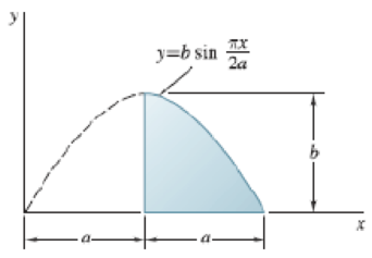
PROBLEM 5.129*
Locate the centroid of the volume generated by revolving the portion of the sine curve shown about the y-axis. (Hint: Use a thin cylindrical shell of radius r and thickness dr as the element of volume.)
Expert Solution & Answer
Want to see the full answer?
Check out a sample textbook solution
Students have asked these similar questions
Student Name:
Student Id:
College of Applied Engineering
Al-Muzahmiyah Branch
Statics (AGE 1330) Section-1483
Quiz-2
Time: 20 minutes
Date: 16/02/2025
Q.1. A swinging door that weighs w=400.0N is supported by
hinges A and B so that the door can swing about a vertical'
axis passing through the hinges (as shown in below figure).
The door has a width of b=1.00m and the door slab has a
uniform mass density. The hinges are placed symmetrically
at the door's edge in such a way that the door's weight is
evenly distributed between them. The hinges are separated
by distance a=2.00m. Find the forces on the hinges when
the door rests half-open. Draw Free body diagram also.
[5 marks]
[CLO 1.2]
Mool
b
ర
a
2.0 m
B
1.0 m
For the walking-beam mechanism shown in Figure 3, find and plot the x and y coordinates of the
position of the coupler point P for one complete revolution of the crank O2A. Use the coordinate
system shown in Figure 3. Hint: Calculate them first with respect to the ground link 0204 and
then transform them into the global XY coordinate system.
y
-1.75
Ꮎ
Ꮎ
4
= 2.33
0242.22
L4
x
AP = 3.06
L2 = 1.0
W2
31°
B
03 L3 = 2.06
P
1
8
5
.06
6
7
P'
The link lengths, gear ratio (2), phase angle (Ø), and the value of 02 for some geared five bar
linkages are defined in Table 2. The linkage configuration and terminology are shown in Figure
2. For the rows assigned, find all possible solutions for angles 03 and 04 by the vector loop
method. Show your work in details: vector loop, vector equations, solution procedure.
Table 2
Row
Link 1 Link 2
Link 3
Link 4
Link 5
λ
Φ
Ө
a
6
1
7
9
4
2
30°
60°
P
y 4
YA
B
b
R4
R3
YA
A
Gear ratio:
a
02
d
05
r5
R5
R2
Phase angle: = 0₂-202
R1
05
02
r2
Figure 2.
04
X
Chapter 5 Solutions
Vector Mechanics for Engineers: Statics and Dynamics
Ch. 5.1 - 5.1 through 5.9 Locate the centroid of the plane...Ch. 5.1 - Locate the centroid of the plane area shown.Ch. 5.1 - Locate the centroid of the plane area shown.Ch. 5.1 - Locate the centroid of the plane area shown.Ch. 5.1 - Locate the centroid of the plane area shown.Ch. 5.1 - Locate the centroid of the plane area shown.Ch. 5.1 - Locate the centroid of the plane area shown.Ch. 5.1 - Locate the centroid of the plane area shown.Ch. 5.1 - Locate the centroid of the plane area shown.Ch. 5.1 - Locate the centroid of the plane area shown.
Ch. 5.1 - Locate the centroid of the plane area shown.Ch. 5.1 - Locate the centroid of the plane area shown.Ch. 5.1 - Locate the centroid of the plane area shown.Ch. 5.1 - Locate the centroid of the plane area shown.Ch. 5.1 - Locate the centroid of the plane area shown.Ch. 5.1 - PROBLEM 5.16 Determine the y coordinate of the...Ch. 5.1 - Show that as r1 approaches r2, the location of the...Ch. 5.1 - Prob. 5.18PCh. 5.1 - Prob. 5.19PCh. 5.1 - A built-up beam is constructed by nailing seven...Ch. 5.1 - The horizontal x axis is drawn through the...Ch. 5.1 - The horizontal x-axis is drawn through the...Ch. 5.1 - PROBLEM 5.23 The first moment of the shaded area...Ch. 5.1 - A thin, homogeneous wire is bent to form the...Ch. 5.1 - A thin, homogeneous wire is bent to form the...Ch. 5.1 - Prob. 5.26PCh. 5.1 - A thin, homogeneous wire is bent to form the...Ch. 5.1 - Prob. 5.28PCh. 5.1 - The frame for a sign is fabricated from thin, flat...Ch. 5.1 - The homogeneous wire ABCD is bent as shown and is...Ch. 5.1 - The homogeneous wire ABCD is bent as shown and is...Ch. 5.1 - Prob. 5.32PCh. 5.1 - Knowing that the distance h has been selected to...Ch. 5.2 - Determine by direct integration the centroid of...Ch. 5.2 - 5.34 through 5.36 Determine by direct integration...Ch. 5.2 - 5.34 through 5.36 Determine by direct integration...Ch. 5.2 - 5.37 through 5.39 Determine by direct integration...Ch. 5.2 - 5.37 through 5.39 Determine by direct integration...Ch. 5.2 - Prob. 5.39PCh. 5.2 - 5.40 and 5.41 Determine by direct integration the...Ch. 5.2 - 5.40 and 5.41 Determine by direct integration the...Ch. 5.2 - 5.42 Determine by direct integration the centroid...Ch. 5.2 - 5.43 and 5.44 Determine by direct integration the...Ch. 5.2 - 5.43 and 5.44 Determine by direct integration the...Ch. 5.2 - 5.45 and 5.46 A homogeneous wire is bent into the...Ch. 5.2 - 5.45 and 5.46 A homogeneous wire is bent into the...Ch. 5.2 - A homogeneous wire is bent into the shape shown....Ch. 5.2 - 5.48 and 5.49 Determine by direct integration the...Ch. 5.2 - Prob. 5.49PCh. 5.2 - Prob. 5.50PCh. 5.2 - Determine the centroid of the area shown when a =...Ch. 5.2 - Determine the volume and the surface area of the...Ch. 5.2 - Determine the volume and the surface area of the...Ch. 5.2 - Determine the volume and the surface area of the...Ch. 5.2 - Determine the volume and the surface area of the...Ch. 5.2 - Determine the volume of the solid generated by...Ch. 5.2 - Prob. 5.57PCh. 5.2 - Prob. 5.58PCh. 5.2 - Prob. 5.59PCh. 5.2 - Determine the capacity, in liters, of the punch...Ch. 5.2 - Determine the volume and total surface area of the...Ch. 5.2 - Prob. 5.62PCh. 5.2 - Determine the total surface area of the solid...Ch. 5.2 - Determine the volume of the brass collar obtained...Ch. 5.2 - The shade for a wall-mounted light is formed from...Ch. 5.3 - 5.66 and 5.67 For the beam and loading shown,...Ch. 5.3 - 5.66 and 5.67 For the beam and loading shown,...Ch. 5.3 - 5.68 through 5.73 Determine the reactions at the...Ch. 5.3 - 5.68 through Determine the reactions at the beam...Ch. 5.3 - 5.68 through 5.73 Determine the reactions at the...Ch. 5.3 - 5.68 through Determine the reactions at the beam...Ch. 5.3 - 5.68 through 5.73 Determine the reactions at the...Ch. 5.3 - 5.68 through 5.73 Determine the reactions at the...Ch. 5.3 - Determine (a) the distance a so that the vertical...Ch. 5.3 - Prob. 5.75PCh. 5.3 - Determine the reactions at the beam supports for...Ch. 5.3 - Determine (a) the distributed load w0 at the end D...Ch. 5.3 - The beam AB supports two concentrated loads and...Ch. 5.3 - For the beam and loading of Prob. 5.78, determine...Ch. 5.3 - The cross section of a concrete dam is as shown....Ch. 5.3 - Prob. 5.81PCh. 5.3 - The dam for a lake is designed to withstand the...Ch. 5.3 - Prob. 5.83PCh. 5.3 - The friction force between a 6 6-ft square sluice...Ch. 5.3 - A freshwater marsh is drained to the ocean through...Ch. 5.3 - Prob. 5.86PCh. 5.3 - The 3 4-m side of an open tank is hinged at its...Ch. 5.3 - Prob. 5.88PCh. 5.3 - A 0.5 0.8-m gate AB is located at the bottom of a...Ch. 5.3 - Prob. 5.90PCh. 5.3 - Prob. 5.91PCh. 5.3 - Prob. 5.92PCh. 5.3 - Prob. 5.93PCh. 5.3 - Prob. 5.94PCh. 5.3 - The square gate AB is held in the position shown...Ch. 5.4 - Consider the composite body shown. Determine (a)...Ch. 5.4 - A cone and a cylinder of the same radius a and...Ch. 5.4 - Determine the location of the center of gravity of...Ch. 5.4 - Prob. 5.99PCh. 5.4 - For the stop bracket shown, locate the x...Ch. 5.4 - Fig. P5.100 and P5.101 5.101 For the stop bracket...Ch. 5.4 - For the machine element shown, locate the x...Ch. 5.4 - Fig. P5.102 and P5.103 5.103 For the machine...Ch. 5.4 - For the machine element shown, locate the y...Ch. 5.4 - For the machine element shown, locate the x...Ch. 5.4 - 5.106 and 5.107 Locate the center of gravity of...Ch. 5.4 - 5.106 and 5.107 Locate the center of gravity of...Ch. 5.4 - A corner reflector for tracking by radar has two...Ch. 5.4 - A wastebasket, designed to fit in the corner of a...Ch. 5.4 - Prob. 5.110PCh. 5.4 - Prob. 5.111PCh. 5.4 - Prob. 5.112PCh. 5.4 - Locate the center of gravity of the sheet-metal...Ch. 5.4 - A thin steel wire with a uniform cross section is...Ch. 5.4 - The frame of a greenhouse is constructed from...Ch. 5.4 - Locate the center of gravity of the figure shown,...Ch. 5.4 - PROBLEM 5.117 Locate the center of gravity of the...Ch. 5.4 - A scratch awl has a plastic handle and a steel...Ch. 5.4 - Prob. 5.119PCh. 5.4 - PROBLEM 5.120 A brass collar, of length 2.5 in.,...Ch. 5.4 - Prob. 5.121PCh. 5.4 - Prob. 5.122PCh. 5.4 - Prob. 5.123PCh. 5.4 - Prob. 5.124PCh. 5.4 - PROBLEM 5.125 Locate the centroid of the volume...Ch. 5.4 - PROBLEM 5.126 Locate the centroid of the volume...Ch. 5.4 - Prob. 5.127PCh. 5.4 - Prob. 5.128PCh. 5.4 - PROBLEM 5.129 Locate the centroid of the volume...Ch. 5.4 - Prob. 5.130PCh. 5.4 - Prob. 5.131PCh. 5.4 - PROBLEM 5.132 The sides and the base of a punch...Ch. 5.4 - Locate the centroid of the section shown, which...Ch. 5.4 - Prob. 5.134PCh. 5.4 - Prob. 5.135PCh. 5.4 - Alter grading a lot, a builder places four stakes...Ch. 5 - 5.137 and 5.138 Locate the centroid of the plane...Ch. 5 - 5.137 and 5.138 Locate the centroid of the plane...Ch. 5 - Prob. 5.139RPCh. 5 - Prob. 5.140RPCh. 5 - Prob. 5.141RPCh. 5 - Prob. 5.142RPCh. 5 - Determine the reactions at the supports for the...Ch. 5 - A beam is subjected to a linearly distributed...Ch. 5 - Prob. 5.145RPCh. 5 - Prob. 5.146RPCh. 5 - An 8-in.-diameter cylindrical duct and a 4 8-in....Ch. 5 - Three brass plates are brazed to a steel pipe to...
Knowledge Booster


Learn more about
Need a deep-dive on the concept behind this application? Look no further. Learn more about this topic, mechanical-engineering and related others by exploring similar questions and additional content below.Similar questions
- Problem 4 A .025 lb bullet C is fired at end B of the 15-lb slender bar AB. The bar is initially at rest, and the initial velocity of the bullet is 1500 ft/s as shown. Assuming that the bullet becomes embedded in the bar, find (a) the angular velocity @2 of the bar immediately after impact, and (b) the percentage loss of kinetic energy as a result of the impact. (c) After the impact, does the bar swing up 90° and reach the horizontal? If it does, what is its angular velocity at this point? Answers: (a). @2=1.6 rad/s; (b). 99.6% loss = (c). Ah2 0.212 ft. The bar does not reach horizontal. y X 4 ft 15 lb V₁ 1500 ft/s 0.025 lb C 30°7 B Aarrow_forwardsubject: combustion please include complete solution, no rounding off, with diagram/explanation etc. In a joule cycle, intake of the compressor is 40,000 cfm at 0.3 psig and 90 deg F. The compression ratio is 6.0 and the inlet temperature at the turbine portion is 1900R while at the exit, it is 15 psi. Calculate for the back work ratio in percent.arrow_forwardsubject: combustion please include complete solution, no rounding off, with diagram/explanation etc. A gasoline engine, utilizing cold air, recorded a work of 431 BTU/lb at a maximum temperature of 3,273 K and 1112 deg F temperature at the beginning of constant volume heat addition. What is the compression ratio?arrow_forward
- subject: combustion please do step by step solution and no rounding off, complete solution with diagram/explanation if needed etc. thank you! Air enters the compressor at 101,320 Pascals, 305.15K, and leaves at a pressure of 0.808MPa. The air is heated to 990.15K in the combustion chamber. For a net output of 2,125,000 Watts, find the rate of flow of air per second.arrow_forwardThe link lengths and the value of 2 and offset for some fourbar crank-slide linkages are defined in Table 1. The linkage configuration and terminology are shown in Figure 1. For the rows assigned, find (a) all possible solutions for angle & and slider position d by vector loop method. (b) the transmission angle corresponding to angle 03. (Hint: Treat the vector R4 as virtual rocker) Show your work in details: vector loop, vector equations, solution procedure. Table 1 Row Link 2 Link 3 Offset Ө a 1.4 4 1 45° b 3 8 2 -30° C 5 20 -5 225° 03 slider axis B X offset Link 2 A R3 Link 3 R4 04 R2 02 R1 d Figure 1. Xarrow_forward4. Two links made of heat treated 6061 aluminum (Sy = 276 MPa, Sys = 160 MPa) are pinned together using a steel dowel pin (Sy = 1398 MPa, Sys = 806 MPa) as shown below. The links are to support a load P with a factor of safety of at least 2.0. Determine if the link will fail first by tearout, direct shear of the pin, bearing stress on the link, or tensile stress at section AA. (Hint: find the load P for each case and choose the case that gives the smallest load.) P 8 mm P 8 mm ¡+A 3 mm →A 10 mm Parrow_forward
- 1. For a feature other than a sphere, circularity is where: A. The axis is a straight line B. The modifier is specified with a size dimension C. All points of the surface intersected by any plane perpendicular to an axis or spine (curved line) are equidistant from that axis or spine D. All points of the surface intersected by any plane passing through a common center are equidistant from that center 2. What type of variation is limited by a circularity toler- ance zone? A. Ovality B. Tapering C. Bending D. Warping 3. How does the Rule #1 boundary affect the application of a circularity tolerance? A. The modifier must be used. B. The feature control frame must be placed next to the size dimension. C. The circularity tolerance value must be less than the limits of size tolerance. D. Circularity cannot be applied where a Rule #1 boundary exists. 4. A circularity tolerance may use a modifier. A. Ø B. F C. M D. ℗ 5. A real-world application for a circularity tolerance is: A. Assembly (i.e.,…arrow_forward3. A steel bar is pinned to a vertical support column by a 10 mm diameter hardened dowel pin, Figure 1. For P = 7500 N, find: a. the shear stress in the pin, b. the direct bearing stress on the hole in the bar, c. the minimum value of d to prevent tearout failure if the steel bar has a shear strength of 175 MPa. support column pin bar thickness of bar = 8 mm h d 150 mmarrow_forwardA press that delivers 115 strokes per minute, each stroke providing a force of 7826 N throughout a distance of 18 mm. The press efficiency is 90% and is driven by a 1749-rpm motor. Determine average torque that must be provided by the motor in the units of N-m.arrow_forward
arrow_back_ios
SEE MORE QUESTIONS
arrow_forward_ios
Recommended textbooks for you
 International Edition---engineering Mechanics: St...Mechanical EngineeringISBN:9781305501607Author:Andrew Pytel And Jaan KiusalaasPublisher:CENGAGE L
International Edition---engineering Mechanics: St...
Mechanical Engineering
ISBN:9781305501607
Author:Andrew Pytel And Jaan Kiusalaas
Publisher:CENGAGE L
Mechanical Engineering: Centroids & Center of Gravity (1 of 35) What is Center of Gravity?; Author: Michel van Biezen;https://www.youtube.com/watch?v=Tkyk-G1rDQg;License: Standard Youtube License