July 17, 1981, Kansas City: The newly opened Hyatt Regency is packed with people listening and dancing to a band playing favorites from the 1940s. Many of the people are crowded onto the walkways that hang like bridges across the wide atrium. Suddenly two of the walkways collapse, falling onto the merrymakers on the main floor. The walkways were suspended one above another on vertical rods and held in place by nuts threaded onto the rods. In the original design, only two long rods were to be used, each extending through all three walkways (Fig. 5-24 a ). If each walkway and the merrymakers on it have a combined mass of M, what is the total mass supported by the threads and two nuts on (a) the lowest walkway and (b) the highest walkway? Apparently someone responsible for the actual construction realized that threading nuts on a rod is impossible except at the ends, so the design was changed: Instead, six rods were used, each connecting two walkways (Fig. 5-24 b ). What now is the total mass supported by the threads and two nuts on (c) the lowest walkway, (d) the upper side of the highest walkway, and (e) the lower side of the highest walkway? It was this design that failed on that tragic night—a simple engineering error. Figure 5.24 Question 7.
July 17, 1981, Kansas City: The newly opened Hyatt Regency is packed with people listening and dancing to a band playing favorites from the 1940s. Many of the people are crowded onto the walkways that hang like bridges across the wide atrium. Suddenly two of the walkways collapse, falling onto the merrymakers on the main floor. The walkways were suspended one above another on vertical rods and held in place by nuts threaded onto the rods. In the original design, only two long rods were to be used, each extending through all three walkways (Fig. 5-24 a ). If each walkway and the merrymakers on it have a combined mass of M, what is the total mass supported by the threads and two nuts on (a) the lowest walkway and (b) the highest walkway? Apparently someone responsible for the actual construction realized that threading nuts on a rod is impossible except at the ends, so the design was changed: Instead, six rods were used, each connecting two walkways (Fig. 5-24 b ). What now is the total mass supported by the threads and two nuts on (c) the lowest walkway, (d) the upper side of the highest walkway, and (e) the lower side of the highest walkway? It was this design that failed on that tragic night—a simple engineering error. Figure 5.24 Question 7.
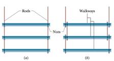
July 17, 1981, Kansas City: The newly opened Hyatt Regency is packed with people listening and dancing to a band playing favorites from the 1940s. Many of the people are crowded onto the walkways that hang like bridges across the wide atrium. Suddenly two of the walkways collapse, falling onto the merrymakers on the main floor.
The walkways were suspended one above another on vertical rods and held in place by nuts threaded onto the rods. In the original design, only two long rods were to be used, each extending through all three walkways (Fig. 5-24a). If each walkway and the merrymakers on it have a combined mass of M, what is the total mass supported by the threads and two nuts on (a) the lowest walkway and (b) the highest walkway?
Apparently someone responsible for the actual construction realized that threading nuts on a rod is impossible except at the ends, so the design was changed: Instead, six rods were used, each connecting two walkways (Fig. 5-24b). What now is the total mass supported by the threads and two nuts on (c) the lowest walkway, (d) the upper side of the highest walkway, and (e) the lower side of the highest walkway? It was this design that failed on that tragic night—a simple engineering error.
4.) The diagram shows the electric field lines of a positively charged conducting sphere of
radius R and charge Q.
A
B
Points A and B are located on the same field line.
A proton is placed at A and released from rest. The magnitude of the work done by the electric field in
moving the proton from A to B is 1.7×10⁻¹⁶ J. Point A is at a distance of 5.0×10⁻²m from the centre of
the sphere. Point B is at a distance of 1.0×10⁻¹ m from the centre of the sphere.
(a) Explain why the electric potential decreases from A to B. [2]
(b) Draw, on the axes, the variation of electric potential V with distance r from the centre of the
sphere.
R
[2]
(c(i)) Calculate the electric potential difference between points A and B. [1]
(c(ii)) Determine the charge Q of the sphere. [2]
(d) The concept of potential is also used in the context of gravitational fields. Suggest why scientists
developed a common terminology to describe different types of fields. [1]
3.) The graph shows how current I varies with potential difference V across a component X.
904
80-
70-
60-
50-
I/MA
40-
30-
20-
10-
0+
0
0.5
1.0 1.5 2.0 2.5 3.0 3.5 4.0 4.5 5.0
VIV
Component X and a cell of negligible internal resistance are placed in a circuit.
A variable resistor R is connected in series with component X. The ammeter reads 20mA.
4.0V
4.0V
Component X and the cell are now placed in a potential divider circuit.
(a) Outline why component X is considered non-ohmic. [1]
(b(i)) Determine the resistance of the variable resistor. [3]
(b(ii)) Calculate the power dissipated in the circuit. [1]
(c(i)) State the range of current that the ammeter can measure as the slider S of the potential divider
is moved from Q to P. [1]
(c(ii)) Describe, by reference to your answer for (c)(i), the advantage of the potential divider
arrangement over the arrangement in (b).
1.) Two long parallel current-carrying wires P and Q are separated by 0.10 m. The current in wire P is 5.0 A.
The magnetic force on a length of 0.50 m of wire P due to the current in wire Q is 2.0 × 10-s N.
(a) State and explain the magnitude of the force on a length of 0.50 m of wire Q due to the current in P. [2]
(b) Calculate the current in wire Q. [2]
(c) Another current-carrying wire R is placed parallel to wires P and Q and halfway between them as shown.
wire P
wire R
wire Q
0.05 m
0.05 m
The net magnetic force on wire Q is now zero.
(c.i) State the direction of the current in R, relative to the current in P.[1]
(c.ii) Deduce the current in R. [2]
Need a deep-dive on the concept behind this application? Look no further. Learn more about this topic, physics and related others by exploring similar questions and additional content below.


 Physics for Scientists and Engineers: Foundations...PhysicsISBN:9781133939146Author:Katz, Debora M.Publisher:Cengage Learning
 Principles of Physics: A Calculus-Based TextPhysicsISBN:9781133104261Author:Raymond A. Serway, John W. JewettPublisher:Cengage Learning
 Physics for Scientists and EngineersPhysicsISBN:9781337553278Author:Raymond A. Serway, John W. JewettPublisher:Cengage Learning
 Physics for Scientists and Engineers with Modern ...PhysicsISBN:9781337553292Author:Raymond A. Serway, John W. JewettPublisher:Cengage Learning
 An Introduction to Physical SciencePhysicsISBN:9781305079137Author:James Shipman, Jerry D. Wilson, Charles A. Higgins, Omar TorresPublisher:Cengage Learning
 College PhysicsPhysicsISBN:9781285737027Author:Raymond A. Serway, Chris VuillePublisher:Cengage Learning