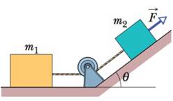
In Fig. 5-64, a force F → of magnitude 12 N is applied to a FedEx box of mass m 2 = 1.0 kg. The force is directed up a plane tilted by θ = 37°. The box is connected by a cord to a UPS box of mass m 1 = 3.0 kg on the floor. The floor, plane, and pulley are frictionless, and the masses of the pulley and cord are negligible. What is the tension in the cord? Figure 5-64 Problem 78.
In Fig. 5-64, a force F → of magnitude 12 N is applied to a FedEx box of mass m 2 = 1.0 kg. The force is directed up a plane tilted by θ = 37°. The box is connected by a cord to a UPS box of mass m 1 = 3.0 kg on the floor. The floor, plane, and pulley are frictionless, and the masses of the pulley and cord are negligible. What is the tension in the cord? Figure 5-64 Problem 78.
In Fig. 5-64, a force
F
→
of magnitude 12 N is applied to a FedEx box of mass m2 = 1.0 kg. The force is directed up a plane tilted by θ = 37°. The box is connected by a cord to a UPS box of mass m1 = 3.0 kg on the floor. The floor, plane, and pulley are frictionless, and the masses of the pulley and cord are negligible. What is the tension in the cord?
3.) The graph shows how current I varies with potential difference V across a component X.
904
80-
70-
60-
50-
I/MA
40-
30-
20-
10-
0+
0
0.5
1.0 1.5 2.0 2.5 3.0 3.5 4.0 4.5 5.0
VIV
Component X and a cell of negligible internal resistance are placed in a circuit.
A variable resistor R is connected in series with component X. The ammeter reads 20mA.
4.0V
4.0V
Component X and the cell are now placed in a potential divider circuit.
(a) Outline why component X is considered non-ohmic. [1]
(b(i)) Determine the resistance of the variable resistor. [3]
(b(ii)) Calculate the power dissipated in the circuit. [1]
(c(i)) State the range of current that the ammeter can measure as the slider S of the potential divider
is moved from Q to P. [1]
(c(ii)) Describe, by reference to your answer for (c)(i), the advantage of the potential divider
arrangement over the arrangement in (b).
1.) Two long parallel current-carrying wires P and Q are separated by 0.10 m. The current in wire P is 5.0 A.
The magnetic force on a length of 0.50 m of wire P due to the current in wire Q is 2.0 × 10-s N.
(a) State and explain the magnitude of the force on a length of 0.50 m of wire Q due to the current in P. [2]
(b) Calculate the current in wire Q. [2]
(c) Another current-carrying wire R is placed parallel to wires P and Q and halfway between them as shown.
wire P
wire R
wire Q
0.05 m
0.05 m
The net magnetic force on wire Q is now zero.
(c.i) State the direction of the current in R, relative to the current in P.[1]
(c.ii) Deduce the current in R. [2]
2.) A 50.0 resistor is connected to a cell of emf 3.00 V. The voltmeter and the ammeter in the circuit are ideal.
V
A
50.00
(a) The current in the ammeter is 59.0 mA. Calculate the internal resistance of the cell.
The circuit is changed by connecting another resistor R in parallel to the 50.0 resistor.
V
A
50.00
R
(b) Explain the effect of this change on R is made of a resistive wire of uniform cross-sectional area 3.1 × 10⁻⁸ m²,
resistivity 4.9 × 10-70m and length L. The resistance of R is given by the equation
R = KL
where k is a constant.
(b.i) the reading of the ammeter. [2]
(b.ii) the reading of the voltmeter. [2]
(c) Calculate k. State an appropriate unit for your answer. [3]
[2]
Biology: Life on Earth with Physiology (11th Edition)
Knowledge Booster
Learn more about
Need a deep-dive on the concept behind this application? Look no further. Learn more about this topic, physics and related others by exploring similar questions and additional content below.


 Physics for Scientists and Engineers: Foundations...PhysicsISBN:9781133939146Author:Katz, Debora M.Publisher:Cengage Learning
 Principles of Physics: A Calculus-Based TextPhysicsISBN:9781133104261Author:Raymond A. Serway, John W. JewettPublisher:Cengage Learning
 Glencoe Physics: Principles and Problems, Student...PhysicsISBN:9780078807213Author:Paul W. ZitzewitzPublisher:Glencoe/McGraw-Hill
 Classical Dynamics of Particles and SystemsPhysicsISBN:9780534408961Author:Stephen T. Thornton, Jerry B. MarionPublisher:Cengage Learning
 College PhysicsPhysicsISBN:9781305952300Author:Raymond A. Serway, Chris VuillePublisher:Cengage Learning
 Physics for Scientists and Engineers, Technology ...PhysicsISBN:9781305116399Author:Raymond A. Serway, John W. JewettPublisher:Cengage Learning