
Concept explainers
Employ Δ–Y conversion techniques as appropriate to determine Rin as labeled in Fig. 5.101.
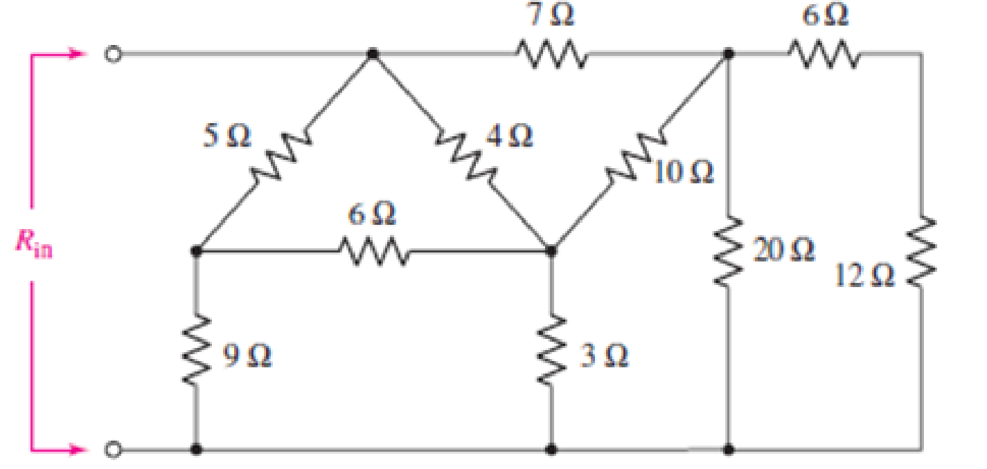
FIGURE 5.101
Employ Δ–Y conversion techniques as appropriate to determine
Answer to Problem 62E
The value of
Explanation of Solution
Formula used:
The expression for the equivalent resistor when resistors are connected in series is as follows:
Here,
The expression for the equivalent resistor when resistors are connected in parallel is as follows:
Here,
The
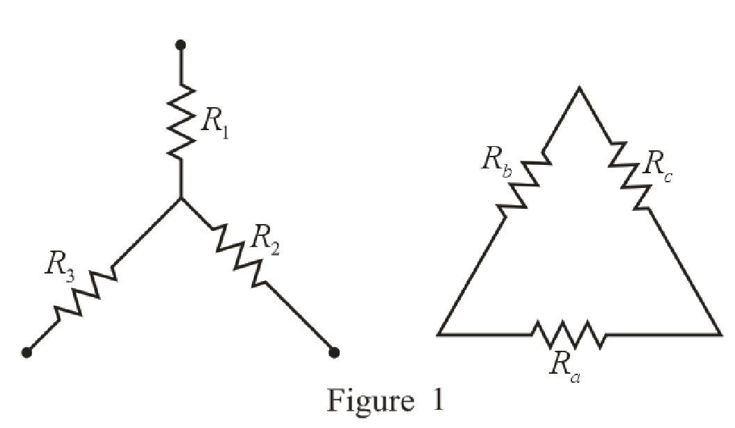
Refer to the redrawn Figure 1:
The expression for the conversion of
Here,
The expression for the conversion of
Calculation:
The redrawn circuit diagram is given in Figure 2:
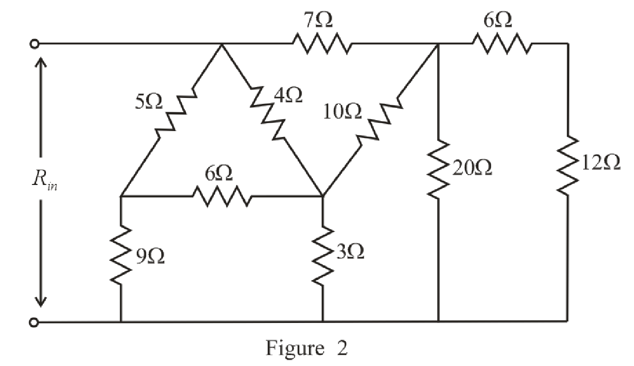
Refer to the redrawn Figure 2:
Substitute
The simplified circuit diagram is given in Figure 3.
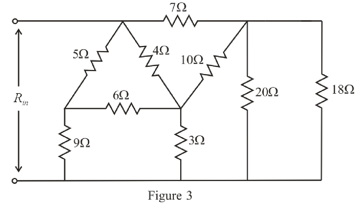
Refer to the redrawn Figure 3:
Substitute
Rearrange the equation for
The simplified circuit diagram is given in Figure 4.
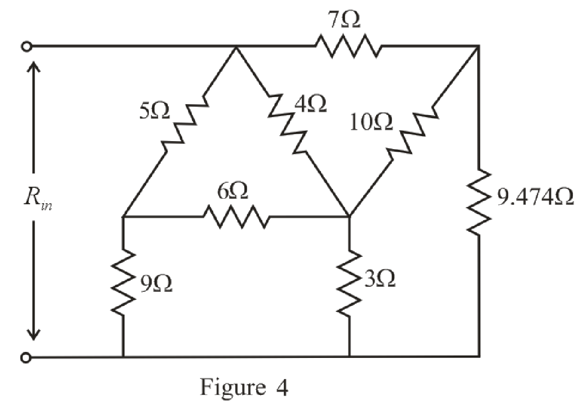
Refer to the redrawn Figure 4:
The
Substitute
Substitute
Substitute
The simplified circuit diagram is given in Figure 5:
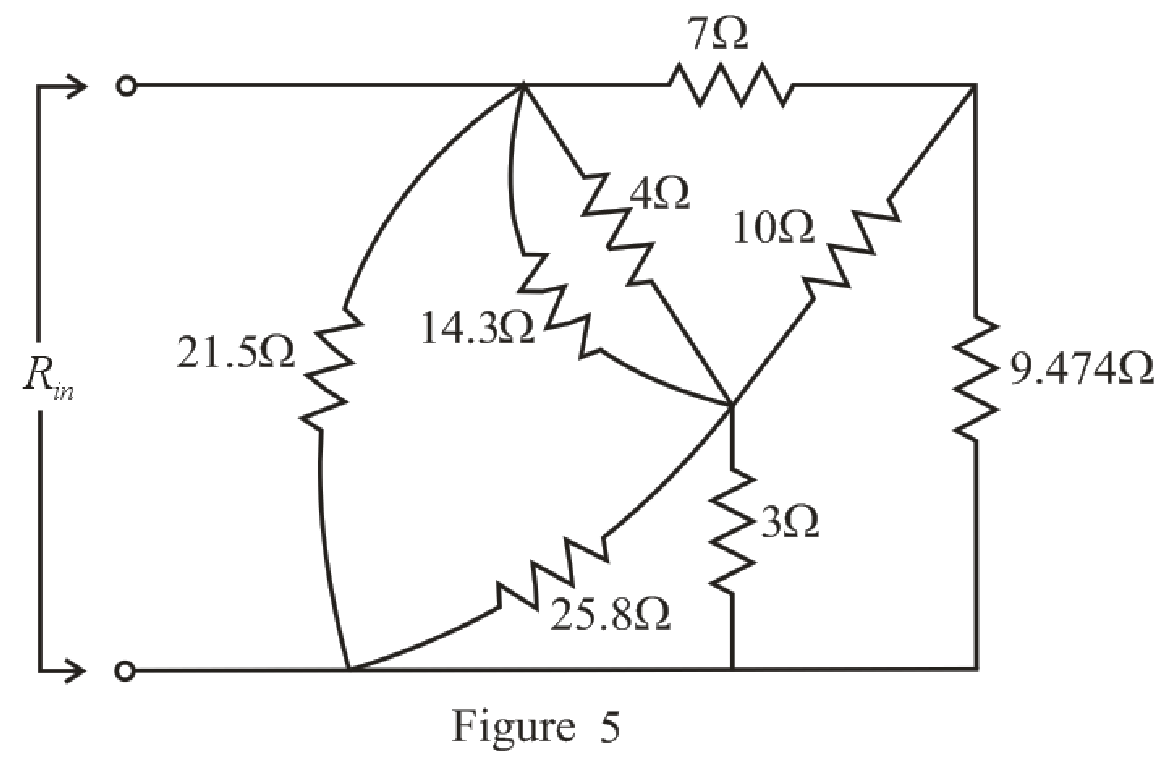
Refer to the redrawn Figure 5:
Substitute
Rearrange the equation for
Substitute
Rearrange the equation for
The simplified circuit diagram is given in Figure 6.
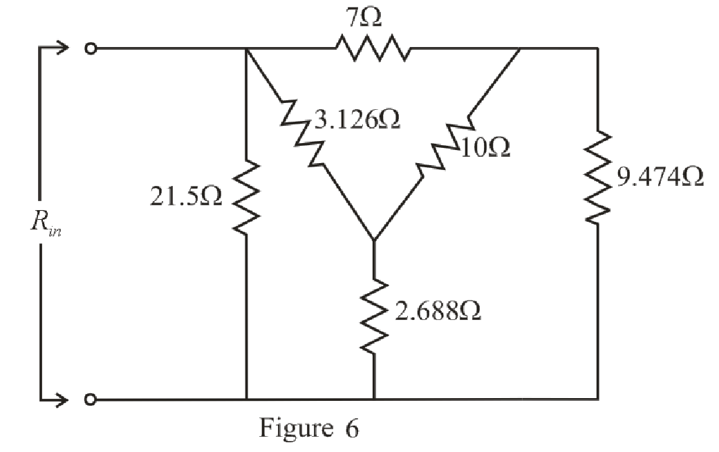
Refer to the redrawn Figure 6:
Substitute
Substitute
Substitute
The simplified circuit diagram is given in Figure 7.
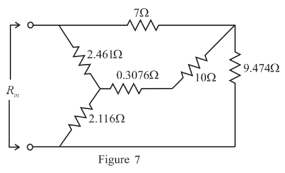
Refer to the redrawn Figure 7:
Substitute
The simplified circuit diagram is given in Figure 8:
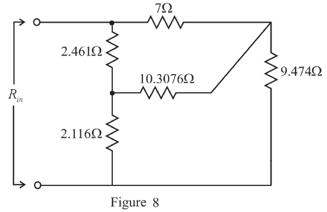
Refer to the redrawn Figure 8:
The
Substitute
Substitute
Substitute
The simplified circuit diagram is given in Figure 9:
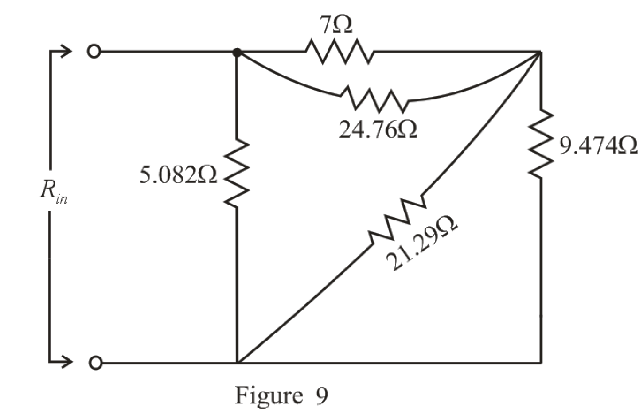
Refer to the redrawn Figure 9:
Substitute
Rearrange the equation for
Substitute
Rearrange the equation for
The simplified circuit diagram is given in Figure 10.
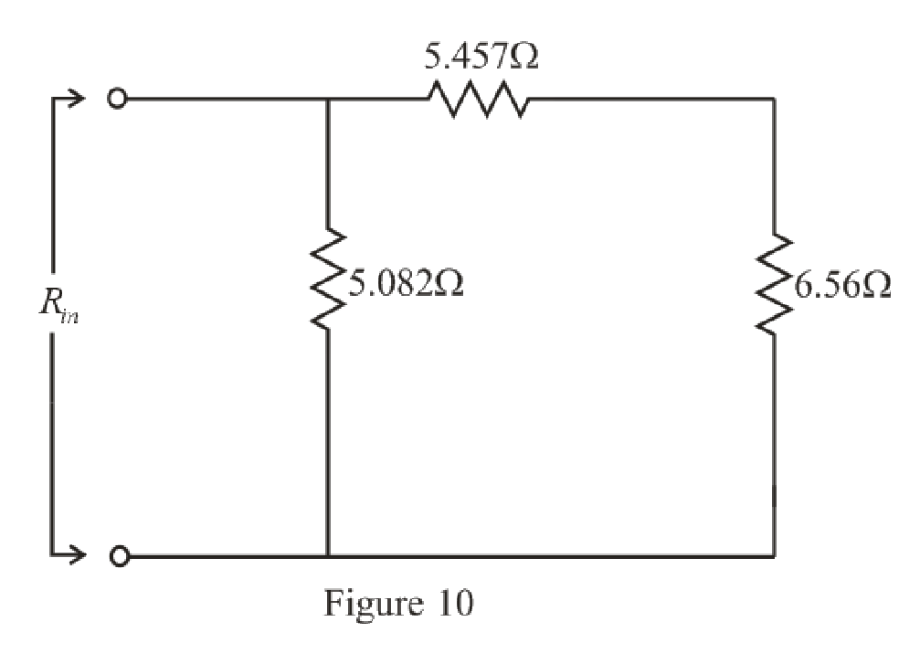
Refer to the redrawn Figure 10:
Substitute
The simplified circuit diagram is given in Figure 11.
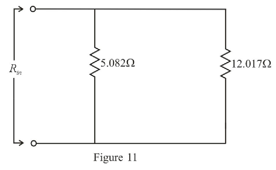
Refer to the redrawn Figure 11:
Substitute
Rearrange the equation for
The simplified circuit diagram is given in Figure 12.
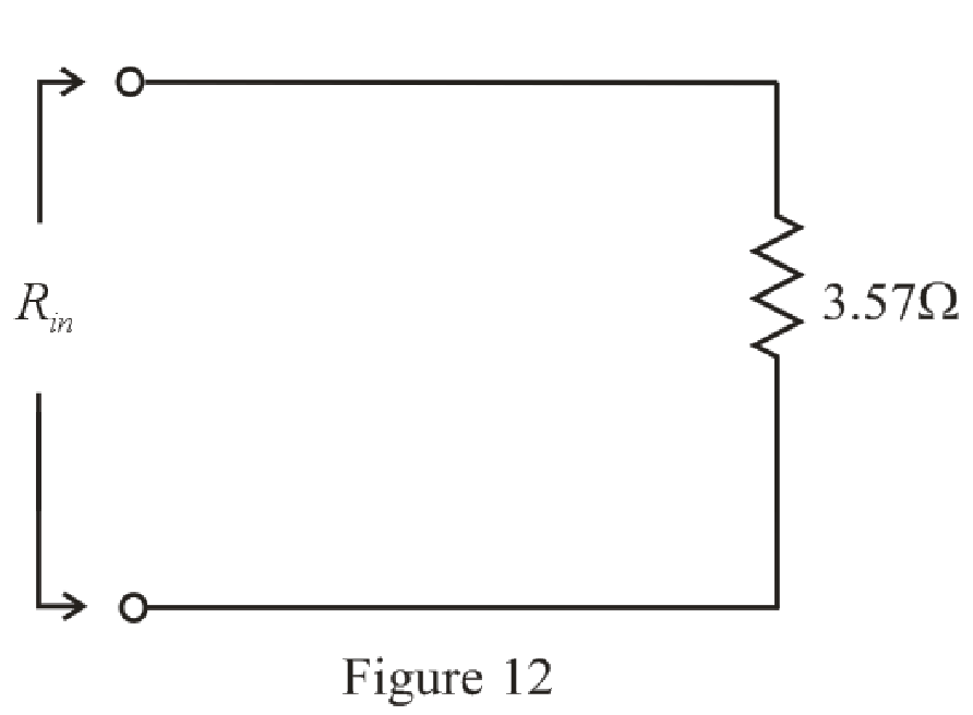
Conclusion:
Thus, the value of
Want to see more full solutions like this?
Chapter 5 Solutions
ENGINEERING CIRCUIT...(LL)>CUSTOM PKG.<
Additional Engineering Textbook Solutions
Problem Solving with C++ (10th Edition)
BASIC BIOMECHANICS
Electric Circuits. (11th Edition)
Concepts Of Programming Languages
Mechanics of Materials (10th Edition)
Thermodynamics: An Engineering Approach
- circuit analysissource transform step by step in the most basic formvo findarrow_forwardCompute the Laplace transform of the following time domain function using only L.T. properties: f(t)=(t-3)eu(t − 2)arrow_forwardcircuit analysisuse source Transform and step by step in the most basic formarrow_forward
- Not: I need also pictures cct diagram and result Question: I need a MATLAB/Simulink model for a Boost Converter used to charge a battery, powered by a PV solar panel. The model should include: 1. A PV solar panel as the input power source. 2. A Boost Converter circuit for voltage regulation. 3. A battery charging system. 4. Simulation results showing voltage, current, and efficiency of the system. Important: Please provide: 1. The Simulink file of the model. 2. Clear screenshots showing the circuit connections in MATLAB/Simulink. 3. Screenshots of the simulation results (voltage, current, efficiency, etc.).arrow_forwardA Butterworth low-pass filter has the following specification: max = 0.5 dB, min =30dB p = 750rad/s and s = 1750rad/si) Determine the TF for Butterworth LP filterii) Q of the polesiii) Determine the half-power frequency 0iv) Determine the actual attenuation at the edge of the pass-band and the edge of the stop-band, (p) and (s).arrow_forwardFind the inverse of Laplace transform s-1 5+5 , Re[s]>-3 (s+1)(s-3) s+5 a) s²(s+3) b) c) (S-1)(s+1)2 d) s+5 , i) Re[s]> 3 ii) Re[s]-1 ii) Re[s] 1 (s-1)(s-2)(s-3)' , i) Re[s]> 3 ii) Re[s]<1 iii) Iarrow_forward1- Find the Laplace transform and the corresponding ROC of the following signals. a) x(t) = [et + et cos(3t)]u(t) b)x(t) = e-alte-atu(t) + eatu(-t), consider a>0. c) x(t)=8(t) +8(t-1)+8(t−2) d) x(t) = u(-1)-u(1) e) x(t) = e-³t sin(2t)u(t)dr f)x(t) =[r³ +sin(2t)]u(t)dt g)x(t)=t2e2 cos(5t) u(t - 1)arrow_forwardThe transfer function of causal LTI system is H(s) = s+1 (s+1)(s+3) Determine the response y(t) when the input x(t) = elt, for the following region of convergence :) Re[s]> -3 ii) Re[s]Re[s]> -3arrow_forwardConsider the signal y(t) = x₁(t-2) x2(-t + 3) where x₁(t) = e−2tu(t) and x2(t) = eu(t). Determine the Laplace transform of y(t) using the properties. Also find the ROC.arrow_forwardConsider the LTI system with the input x(t) = eu(t) and the impulse response h(t) = e−2tu(t). a) Determine the Laplace transform of x(t) and h(t). b) Using convolutional property, determine the Laplace transform of the output y(t). Find the ROC for each case.arrow_forward2) a) Plot the voltage transfer characteristic of the circuit below. Assume diode and zener are ideal with VDon=0V (20Pts) view 1K 1, B-100, VBE =0,7V ovo VCEsat = 0V, 2K It 10 V 8V zenerarrow_forwardcircuit dchow find vth step by step rth find RL that enables the circuit to deliver maximum power to terminal then plot norton cırcuitarrow_forwardarrow_back_iosSEE MORE QUESTIONSarrow_forward_ios
 Introductory Circuit Analysis (13th Edition)Electrical EngineeringISBN:9780133923605Author:Robert L. BoylestadPublisher:PEARSON
 Delmar's Standard Textbook Of ElectricityElectrical EngineeringISBN:9781337900348Author:Stephen L. HermanPublisher:Cengage Learning
 Programmable Logic ControllersElectrical EngineeringISBN:9780073373843Author:Frank D. PetruzellaPublisher:McGraw-Hill Education
 Fundamentals of Electric CircuitsElectrical EngineeringISBN:9780078028229Author:Charles K Alexander, Matthew SadikuPublisher:McGraw-Hill Education
 Electric Circuits. (11th Edition)Electrical EngineeringISBN:9780134746968Author:James W. Nilsson, Susan RiedelPublisher:PEARSON
 Engineering ElectromagneticsElectrical EngineeringISBN:9780078028151Author:Hayt, William H. (william Hart), Jr, BUCK, John A.Publisher:Mcgraw-hill Education,


