
ENGINEERING CIRCUIT...(LL)>CUSTOM PKG.<
9th Edition
ISBN: 9781260540666
Author: Hayt
Publisher: MCG CUSTOM
expand_more
expand_more
format_list_bulleted
Concept explainers
Videos
Textbook Question
Chapter 5, Problem 20E
(a) Making use of repeated source transformations, reduce the circuit of Fig. 5.64 such that it contains a single voltage source, the 17 Ω resistor, and one other resistor. (b) Calculate the power dissipated by the 17 Ω resistor. (c) Verify your results by simulating both circuits.
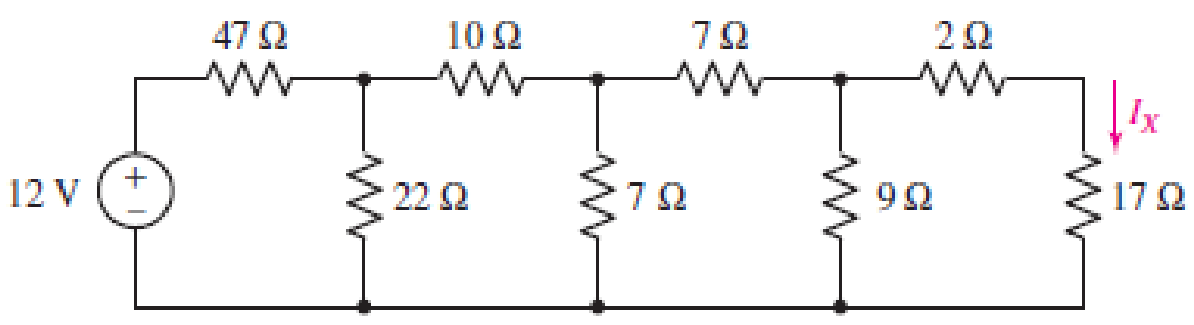
■ FIGURE 5.64
Expert Solution & Answer

Trending nowThis is a popular solution!

Students have asked these similar questions
Calculate the magnitude of the current in the coils e1, e2 of the magnetic circuit, if:
ɸa = 3,00 x 10⁻³ Wb, φb = 0,80 x 10⁻³ Wb, ɸc = 2,20 x 10⁻³ Wb
L AB = 0,10 m, L AFEB = L ACDB = 0,40 m
AAB = 5,0 cm2 A AFEB = A ACDB = 20 cm2
Material characteristics
H (At/m) 240 350 530 1300 5000 9000
B (T) 0,7 0,9 1,1 1,3 1,5 1,6
Power systems
Explain the advantages and disadvantages of using silicon (Si) anode versus graphitic anode (C6) and write charging reactions for these anodes.
Explain the effect of increasing state of charge window (SOC) of lithium battery and how SOC-window impact energy density and cycle life of the battery.
Chapter 5 Solutions
ENGINEERING CIRCUIT...(LL)>CUSTOM PKG.<
Ch. 5.1 - For the circuit of Fig. 5.4, use superposition to...Ch. 5.2 - For the circuit of Fig. 5.7, use superposition to...Ch. 5.2 - For the circuit of Fig. 5.18, compute the current...Ch. 5.2 - For the circuit of Fig. 5.20, compute the voltage...Ch. 5.3 - Using repeated source transformations, determine...Ch. 5.3 - Use Thvenins theorem to find the current through...Ch. 5.3 - Determine the Thvenin and Norton equivalents of...Ch. 5.3 - Find the Thvenin equivalent for the network of...Ch. 5.3 - Find the Thvenin equivalent for the network of...Ch. 5.4 - Consider the circuit of Fig. 5.43. FIGURE 5.43...
Ch. 5.5 - Prob. 11PCh. 5 - Linear systems are so easy to work with that...Ch. 5 - Prob. 2ECh. 5 - Prob. 3ECh. 5 - (a) Employ superposition to determine the current...Ch. 5 - (a) Using superposition to consider each source...Ch. 5 - (a) Determine the individual contributions of each...Ch. 5 - (a) Determine the individual contributions of each...Ch. 5 - After studying the circuit of Fig. 5.53, change...Ch. 5 - Consider the three circuits shown in Fig. 5.54....Ch. 5 - (a) Using superposition, determine the voltage...Ch. 5 - Employ superposition principles to obtain a value...Ch. 5 - (a) Employ superposition to determine the...Ch. 5 - Perform an appropriate source transformation on...Ch. 5 - (a) For the circuit of Fig. 5.59, plot iL versus...Ch. 5 - Determine the current labeled I in the circuit of...Ch. 5 - Verify that the power absorbed by the 7 resistor...Ch. 5 - (a) Determine the current labeled i in the circuit...Ch. 5 - (a) Using repeated source transformations, reduce...Ch. 5 - Prob. 19ECh. 5 - (a) Making use of repeated source transformations,...Ch. 5 - Prob. 21ECh. 5 - (a) With the assistance of source transformations,...Ch. 5 - For the circuit in Fig. 5.67 transform all...Ch. 5 - Prob. 24ECh. 5 - (a) Referring to Fig. 5.69, determine the Thevenin...Ch. 5 - (a) With respect to the circuit depicted in Fig....Ch. 5 - (a) Obtain the Norton equivalent of the network...Ch. 5 - (a) Determine the Thevenin equivalent of the...Ch. 5 - Referring to the circuit of Fig. 5.71: (a)...Ch. 5 - Prob. 30ECh. 5 - (a) Employ Thvenins theorem to obtain a...Ch. 5 - Prob. 32ECh. 5 - Determine the Norton equivalent of the circuit...Ch. 5 - For the circuit of Fig. 5.75: (a) Employ Nortons...Ch. 5 - (a) Obtain a value for the Thvenin equivalent...Ch. 5 - Prob. 36ECh. 5 - Obtain a value for the Thvenin equivalent...Ch. 5 - With regard to the network depicted in Fig. 5.79,...Ch. 5 - Determine the Thvenin and Norton equivalents of...Ch. 5 - Determine the Norton equivalent of the circuit...Ch. 5 - Prob. 41ECh. 5 - Determine the Thvenin and Norton equivalents of...Ch. 5 - Prob. 43ECh. 5 - Prob. 44ECh. 5 - Prob. 45ECh. 5 - (a) For the simple circuit of Fig. 5.87, find the...Ch. 5 - For the circuit drawn in Fig. 5.88, (a) determine...Ch. 5 - Study the circuit of Fig. 5.89. (a) Determine the...Ch. 5 - Prob. 49ECh. 5 - Prob. 50ECh. 5 - With reference to the circuit of Fig. 5.91, (a)...Ch. 5 - Prob. 52ECh. 5 - Select a value for RL in Fig. 5.93 such that it...Ch. 5 - Determine what value of resistance would absorb...Ch. 5 - Derive the equations required to convert from a...Ch. 5 - Convert the - (or "-") connected networks in Fig....Ch. 5 - Convert the Y-(or T-) connected networks in Fig....Ch. 5 - For the network of Fig. 5.97, select a value of R...Ch. 5 - For the network of Fig. 5.98, select a value of R...Ch. 5 - Prob. 60ECh. 5 - Calculate Rin as indicated in Fig.5.100. FIGURE...Ch. 5 - Employ Y conversion techniques as appropriate to...Ch. 5 - Prob. 63ECh. 5 - (a) Use appropriate techniques to obtain both the...Ch. 5 - (a) For the network in Fig. 5.104, replace the...Ch. 5 - Prob. 66ECh. 5 - Prob. 67ECh. 5 - A 2.57 load is connected between terminals a and...Ch. 5 - A load resistor is connected across the open...Ch. 5 - A backup is required for the circuit depicted in...Ch. 5 - (a) Explain in general terms how source...Ch. 5 - The load resistor in Fig. 5.108 can safely...Ch. 5 - Prob. 74ECh. 5 - As part of a security system, a very thin 100 ...Ch. 5 - With respect to the circuit in Fig. 5.90, (a)...
Additional Engineering Textbook Solutions
Find more solutions based on key concepts
The following C++ program will not compile because the lines have been mixed up. cout Success\n; cout Success...
Starting Out with C++ from Control Structures to Objects (9th Edition)
Consider the adage Never ask a question for which you do not want the answer. a. Is following that adage ethica...
Experiencing MIS
The solid steel shaft AC has a diameter of 25 mm and is supported by smooth bearings at D and E. It is coupled ...
Mechanics of Materials (10th Edition)
1.2 Explain the difference between geodetic and plane
surveys,
Elementary Surveying: An Introduction To Geomatics (15th Edition)
The job of the _____ is to fetch instructions, carry out the operations commanded by the instructions, and prod...
Starting Out With Visual Basic (8th Edition)
What is an uninitialized variable?
Starting Out with Programming Logic and Design (5th Edition) (What's New in Computer Science)
Knowledge Booster


Learn more about
Need a deep-dive on the concept behind this application? Look no further. Learn more about this topic, electrical-engineering and related others by exploring similar questions and additional content below.Similar questions
- Don't use guidelines okk just solve all accurate only 100% sure experts solve it correct complete solutions okkkarrow_forward3. Consider the circuit, in which R₁ = 10 KQ2, R2 = 5 KQ, R3 = 1 KQ, and RE = 8 KQ. The supply voltages are +Vcc = 10 V and -VEE = -5 V. Other parameters are ẞF = 100, VBE(On) = 0.7 V, and VCE(Sat) 0.2 V. Rc value will be specified later. (a) (3 points) Draw the dc equivalent circuit of the circuit. VI +Vcc Rc R2 RI R₁ RE -VEE υο R3 (b) Find the Thevenin equivalent voltage source VEQ and input resistance REQ of the DC equivalent circuit. Show your work. +Vcc Rc UC VEQ www REQ VE VEQ = REQ = ΚΩ RE VEEarrow_forward5. Consider the ac equivalent circuit of an amplifier, where RE = 1 KS2, gm = 0.05 S, and Υπ= 2Κ Ω. (a) Redraw the ac equivalent circuit using the hybrid-pi small signal model for BJTS. Include ro in the model. R₁ ww Vi RB ww + RL Vo RE (b) Find the terminal resistance RIB using the circuit obtained in (a). Ignore ro. Show your work. (Don't use formula for RiB.)arrow_forward
- 4. Consider the circuit. Use the symbol || to indicate the parallel of resistors in the following questions. (a) Express the input resistance Rin in terms of the terminal resistance and other necessary resistor values. (In other words, RiB, Ric, and RIE are given.) C₁ R₁ R₂ +Vcc Rc C3 R3 C2 ی RE -VEE (b) Express the output resistance Rout in terms of the terminal resistance and other necessary resistor values. (In other words, RiB, Ric and RiE are given.) (c) Express the voltage gain A₁ = ∞ in terms of terminal voltage gain Avt, the terminal Vi resistance, and other necessary resistor values. (Avt, RiB, Ric and R₁E are given.) +51arrow_forward2. ẞ 100, VBE(on)= 0.7 V, and VCE(sat) = 0.2 V for the BJT. We want to find the Q-point through the following steps. Show your work. a) Find the bias voltage VTH Using Thevenin's equivalent circuit. R1|| R2 www +5 V R₁ = 20 k IB VTH Answer: VTH = V b) Find the base current voltage IB. www. Answer: IB = μA (note the unit.) c) Find the collector voltage Vc (with reference to the ground). RC= 2.3 k B E R₂ = 30 k -5 V www R₁ = 5 ΚΩ ww AHI› RE= 5 ΚΩarrow_forward3. Consider the circuit, in which R₁ = 10 KQ2, R2 = 5 KQ, R3 = 1 KQ, and RE = 8 KQ. The supply voltages are +Vcc = 10 V and -VEE = -5 V. Other parameters are ẞF = 100, VBE(On) = 0.7 V, and VCE(Sat) 0.2 V. Rc value will be specified later. (a) (3 points) Draw the dc equivalent circuit of the circuit. VI +Vcc Rc R2 RI R₁ RE -VEE υο R3 (b) Find the Thevenin equivalent voltage source VEQ and input resistance REQ of the DC equivalent circuit. Show your work. +Vcc Rc UC VEQ www REQ VE VEQ = REQ = ΚΩ RE VEEarrow_forward
- The solution is with a pen and paper. Really not smartarrow_forward1. Consider the following mechanical system. Obtain the differential equation model for the system. Write the transfer function of the system also. Note here, input u(t) is force and output x(t) is the displacement of the mass. x (Output) k1 k2 www u(t) m (Input force) No frictionarrow_forwardNO AI PLEASEarrow_forward
arrow_back_ios
SEE MORE QUESTIONS
arrow_forward_ios
Recommended textbooks for you
 Introductory Circuit Analysis (13th Edition)Electrical EngineeringISBN:9780133923605Author:Robert L. BoylestadPublisher:PEARSON
 Delmar's Standard Textbook Of ElectricityElectrical EngineeringISBN:9781337900348Author:Stephen L. HermanPublisher:Cengage Learning
 Programmable Logic ControllersElectrical EngineeringISBN:9780073373843Author:Frank D. PetruzellaPublisher:McGraw-Hill Education
 Fundamentals of Electric CircuitsElectrical EngineeringISBN:9780078028229Author:Charles K Alexander, Matthew SadikuPublisher:McGraw-Hill Education
 Electric Circuits. (11th Edition)Electrical EngineeringISBN:9780134746968Author:James W. Nilsson, Susan RiedelPublisher:PEARSON
 Engineering ElectromagneticsElectrical EngineeringISBN:9780078028151Author:Hayt, William H. (william Hart), Jr, BUCK, John A.Publisher:Mcgraw-hill Education,
Introductory Circuit Analysis (13th Edition)
Electrical Engineering
ISBN:9780133923605
Author:Robert L. Boylestad
Publisher:PEARSON
Delmar's Standard Textbook Of Electricity
Electrical Engineering
ISBN:9781337900348
Author:Stephen L. Herman
Publisher:Cengage Learning
Programmable Logic Controllers
Electrical Engineering
ISBN:9780073373843
Author:Frank D. Petruzella
Publisher:McGraw-Hill Education
Fundamentals of Electric Circuits
Electrical Engineering
ISBN:9780078028229
Author:Charles K Alexander, Matthew Sadiku
Publisher:McGraw-Hill Education
Electric Circuits. (11th Edition)
Electrical Engineering
ISBN:9780134746968
Author:James W. Nilsson, Susan Riedel
Publisher:PEARSON
Engineering Electromagnetics
Electrical Engineering
ISBN:9780078028151
Author:Hayt, William H. (william Hart), Jr, BUCK, John A.
Publisher:Mcgraw-hill Education,
Latches and Flip-Flops 1 - The SR Latch; Author: Computer Science;https://www.youtube.com/watch?v=-aQH0ybMd3U;License: Standard Youtube License