
ENGINEERING CIRCUIT...(LL)>CUSTOM PKG.<
9th Edition
ISBN: 9781260540666
Author: Hayt
Publisher: MCG CUSTOM
expand_more
expand_more
format_list_bulleted
Concept explainers
Videos
Textbook Question
Chapter 5, Problem 15E
Determine the current labeled I in the circuit of Fig. 5.60 by first performing source transformations and parallel–series combinations as required to reduce the circuit to only three elements.
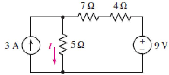
■ FIGURE 5.60
Expert Solution & Answer

Trending nowThis is a popular solution!

Students have asked these similar questions
Solve on Paper not using chatgpt
I need help with this problem and an explanation of the solution for the image described below. (Introduction to Signals and Systems)
Given 10AWG, copper, RHW, 44 C, 3 conductors, find ampacity
Chapter 5 Solutions
ENGINEERING CIRCUIT...(LL)>CUSTOM PKG.<
Ch. 5.1 - For the circuit of Fig. 5.4, use superposition to...Ch. 5.2 - For the circuit of Fig. 5.7, use superposition to...Ch. 5.2 - For the circuit of Fig. 5.18, compute the current...Ch. 5.2 - For the circuit of Fig. 5.20, compute the voltage...Ch. 5.3 - Using repeated source transformations, determine...Ch. 5.3 - Use Thvenins theorem to find the current through...Ch. 5.3 - Determine the Thvenin and Norton equivalents of...Ch. 5.3 - Find the Thvenin equivalent for the network of...Ch. 5.3 - Find the Thvenin equivalent for the network of...Ch. 5.4 - Consider the circuit of Fig. 5.43. FIGURE 5.43...
Ch. 5.5 - Prob. 11PCh. 5 - Linear systems are so easy to work with that...Ch. 5 - Prob. 2ECh. 5 - Prob. 3ECh. 5 - (a) Employ superposition to determine the current...Ch. 5 - (a) Using superposition to consider each source...Ch. 5 - (a) Determine the individual contributions of each...Ch. 5 - (a) Determine the individual contributions of each...Ch. 5 - After studying the circuit of Fig. 5.53, change...Ch. 5 - Consider the three circuits shown in Fig. 5.54....Ch. 5 - (a) Using superposition, determine the voltage...Ch. 5 - Employ superposition principles to obtain a value...Ch. 5 - (a) Employ superposition to determine the...Ch. 5 - Perform an appropriate source transformation on...Ch. 5 - (a) For the circuit of Fig. 5.59, plot iL versus...Ch. 5 - Determine the current labeled I in the circuit of...Ch. 5 - Verify that the power absorbed by the 7 resistor...Ch. 5 - (a) Determine the current labeled i in the circuit...Ch. 5 - (a) Using repeated source transformations, reduce...Ch. 5 - Prob. 19ECh. 5 - (a) Making use of repeated source transformations,...Ch. 5 - Prob. 21ECh. 5 - (a) With the assistance of source transformations,...Ch. 5 - For the circuit in Fig. 5.67 transform all...Ch. 5 - Prob. 24ECh. 5 - (a) Referring to Fig. 5.69, determine the Thevenin...Ch. 5 - (a) With respect to the circuit depicted in Fig....Ch. 5 - (a) Obtain the Norton equivalent of the network...Ch. 5 - (a) Determine the Thevenin equivalent of the...Ch. 5 - Referring to the circuit of Fig. 5.71: (a)...Ch. 5 - Prob. 30ECh. 5 - (a) Employ Thvenins theorem to obtain a...Ch. 5 - Prob. 32ECh. 5 - Determine the Norton equivalent of the circuit...Ch. 5 - For the circuit of Fig. 5.75: (a) Employ Nortons...Ch. 5 - (a) Obtain a value for the Thvenin equivalent...Ch. 5 - Prob. 36ECh. 5 - Obtain a value for the Thvenin equivalent...Ch. 5 - With regard to the network depicted in Fig. 5.79,...Ch. 5 - Determine the Thvenin and Norton equivalents of...Ch. 5 - Determine the Norton equivalent of the circuit...Ch. 5 - Prob. 41ECh. 5 - Determine the Thvenin and Norton equivalents of...Ch. 5 - Prob. 43ECh. 5 - Prob. 44ECh. 5 - Prob. 45ECh. 5 - (a) For the simple circuit of Fig. 5.87, find the...Ch. 5 - For the circuit drawn in Fig. 5.88, (a) determine...Ch. 5 - Study the circuit of Fig. 5.89. (a) Determine the...Ch. 5 - Prob. 49ECh. 5 - Prob. 50ECh. 5 - With reference to the circuit of Fig. 5.91, (a)...Ch. 5 - Prob. 52ECh. 5 - Select a value for RL in Fig. 5.93 such that it...Ch. 5 - Determine what value of resistance would absorb...Ch. 5 - Derive the equations required to convert from a...Ch. 5 - Convert the - (or "-") connected networks in Fig....Ch. 5 - Convert the Y-(or T-) connected networks in Fig....Ch. 5 - For the network of Fig. 5.97, select a value of R...Ch. 5 - For the network of Fig. 5.98, select a value of R...Ch. 5 - Prob. 60ECh. 5 - Calculate Rin as indicated in Fig.5.100. FIGURE...Ch. 5 - Employ Y conversion techniques as appropriate to...Ch. 5 - Prob. 63ECh. 5 - (a) Use appropriate techniques to obtain both the...Ch. 5 - (a) For the network in Fig. 5.104, replace the...Ch. 5 - Prob. 66ECh. 5 - Prob. 67ECh. 5 - A 2.57 load is connected between terminals a and...Ch. 5 - A load resistor is connected across the open...Ch. 5 - A backup is required for the circuit depicted in...Ch. 5 - (a) Explain in general terms how source...Ch. 5 - The load resistor in Fig. 5.108 can safely...Ch. 5 - Prob. 74ECh. 5 - As part of a security system, a very thin 100 ...Ch. 5 - With respect to the circuit in Fig. 5.90, (a)...
Knowledge Booster


Learn more about
Need a deep-dive on the concept behind this application? Look no further. Learn more about this topic, electrical-engineering and related others by exploring similar questions and additional content below.Similar questions
- Solve on paper not using chatgptarrow_forwardAssume that a building manager instructed you to install a water heater. The specs on the water heater nameplate reveals the following 240V, 2PH, 60HZ, 5.7KW. The manager insisted for the installation to be done with 10 AWG copper THWN-2 conductor, the length of run is 1200 FT away from the service panel. Calculate the voltage after the installation.arrow_forwardPlease confirm that my solution is correct, especially the block diagram. Please DRAW (not type) what the block diagram would look like if it's incorrect. thank youarrow_forward
- use this code on the bottom to answer the question in the photo clc; clearvars; % Read the file [y, Fs] = audioread('106miles.wav'); N = length(y); Nfft = 2^nextpow2(N); dt = 1/Fs; t = (0:dt:(N-1)*dt)'; % Ensure t is a column vector y = y - mean(y); % Remove DC component (if not already zero-mean) % Carrier signal (25 kHz) fc = 25000; % Carrier frequency in Hz carrier = cos(2 * pi * fc * t); % DSB-SC Modulation modulated_signal = y .* carrier; % Plot Time Domain Signal figure; subplot(2,1,1); plot(t, y); title('Original Signal (Time Domain)'); xlabel('Time (s)'); ylabel('Amplitude'); subplot(2,1,2); plot(t, modulated_signal); title('DSB-SC Modulated Signal (Time Domain)'); xlabel('Time (s)'); ylabel('Amplitude'); % Frequency Domain (FFT) Y = fft(y, Nfft) / Nfft; Modulated_Y = fft(modulated_signal, Nfft) / Nfft; f = Fs * (0:(Nfft/2)) / Nfft; % Frequency vector % Plot Frequency Domain Signal figure; subplot(2,1,1); plot(f, abs(Y(1:Nfft/2+1))); title('Original Signal…arrow_forward5-9 A 230 V shunt motor has a nominal arma- ture current of 60 A. If the armature resist- ance is 0.152, calculate the following: a. The counter-emf [V] b. The power supplied to the armature [W] c. The mechanical power developed by the motor, [kW] and [hp] 5-10 a. In Problem 5-9 calculate the initial start- ing current if the motor is directly con- nected across the 230 V line. b. Calculate the value of the starting resistor needed to limit the initial current to 115 A.arrow_forwardhow to solve this?arrow_forward
- For the circuit in Fig. P8.52, choose the load impedance ZLso that the power dissipated in it is a maximum. How much powerwill that be?arrow_forwardhow to solve the attached question? please explain or give reference where required in the solution.arrow_forwardHANDWRITTEN SOLUTION REQUIRED NOT USING CHATGPTarrow_forward
arrow_back_ios
SEE MORE QUESTIONS
arrow_forward_ios
Recommended textbooks for you
 Introductory Circuit Analysis (13th Edition)Electrical EngineeringISBN:9780133923605Author:Robert L. BoylestadPublisher:PEARSON
 Delmar's Standard Textbook Of ElectricityElectrical EngineeringISBN:9781337900348Author:Stephen L. HermanPublisher:Cengage Learning
 Programmable Logic ControllersElectrical EngineeringISBN:9780073373843Author:Frank D. PetruzellaPublisher:McGraw-Hill Education
 Fundamentals of Electric CircuitsElectrical EngineeringISBN:9780078028229Author:Charles K Alexander, Matthew SadikuPublisher:McGraw-Hill Education
 Electric Circuits. (11th Edition)Electrical EngineeringISBN:9780134746968Author:James W. Nilsson, Susan RiedelPublisher:PEARSON
 Engineering ElectromagneticsElectrical EngineeringISBN:9780078028151Author:Hayt, William H. (william Hart), Jr, BUCK, John A.Publisher:Mcgraw-hill Education,
Introductory Circuit Analysis (13th Edition)
Electrical Engineering
ISBN:9780133923605
Author:Robert L. Boylestad
Publisher:PEARSON
Delmar's Standard Textbook Of Electricity
Electrical Engineering
ISBN:9781337900348
Author:Stephen L. Herman
Publisher:Cengage Learning
Programmable Logic Controllers
Electrical Engineering
ISBN:9780073373843
Author:Frank D. Petruzella
Publisher:McGraw-Hill Education
Fundamentals of Electric Circuits
Electrical Engineering
ISBN:9780078028229
Author:Charles K Alexander, Matthew Sadiku
Publisher:McGraw-Hill Education
Electric Circuits. (11th Edition)
Electrical Engineering
ISBN:9780134746968
Author:James W. Nilsson, Susan Riedel
Publisher:PEARSON
Engineering Electromagnetics
Electrical Engineering
ISBN:9780078028151
Author:Hayt, William H. (william Hart), Jr, BUCK, John A.
Publisher:Mcgraw-hill Education,
Latches and Flip-Flops 1 - The SR Latch; Author: Computer Science;https://www.youtube.com/watch?v=-aQH0ybMd3U;License: Standard Youtube License