
Videos
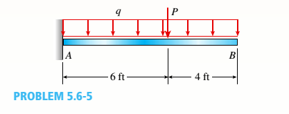
A cantilever beanie B is loaded by a uniform load q and a concentrated load P, as shown in the figure.
- Select the most economical steel C shape from Table F-3(a) in Appendix F; use q = 20 lb/ft and P = 300 lb (assume allowable normal stress is cra= IS ksi).
Note: For parts (a), (b), and (c), revise your initial beam selection as needed to include the distributed weight of the beam in addition to uniform load q.
(a)
The most economical steel
Answer to Problem 5.6.5P
The most economical steel
Explanation of Solution
Given information:
The uniform distributed load is
The following figure shows the free body diagram:
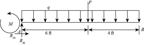
Figure-(1)
Write the expression for the maximum moment of beam.
Here, the load is
Write the expression for the section modulus.
Here, the maximum stress is
Write the expression for the maximum stress.
Here, the maximum stress is
Calculation:
Substitute
Substitute
Refer to the table
Substitute
Substitute
Here, the maximum stress is greater than the calculated stress, so we neglect this section.
Refer to the table
Substitute
Substitute
Hence, from the table “Appendix F” we will use the value
Conclusion:
The most economical steel
(b)
The most economical steel
Answer to Problem 5.6.5P
The most economical steel
Explanation of Solution
Given Information:
The uniform distributed load is
Write the expression for the maximum moment of beam.
Write the expression for the section modulus.
Write the expression for the maximum stress.
Calculation:
Substitute for
Substitute
Refer to the table
Substitute
Substitute
Here, the maximum stress is greater than the calculated stress, so we neglect this section.
Refer to the table
Substitute
Substitute
Hence, from the table “Appendix F” we will use the value
Conclusion:
The maximum value of load
(c)
The most economical steel
Answer to Problem 5.6.5P
The most economical steel
Explanation of Solution
Given Information:
The uniform distributed load is
Write the expression for the maximum moment of beam.
Write the expression for the section modulus.
Write the expression for the maximum stress.
Calculation:
Substitute
Substitute
Refer to the table
Substitute
Substitute
Hence, from the table “Appendix F” we will use the value
Conclusion:
The maximum value of load
Want to see more full solutions like this?
Chapter 5 Solutions
Bundle: Mechanics Of Materials, Loose-leaf Version, 9th + Mindtap Engineering, 2 Terms (12 Months) Printed Access Card


- The force F={25i−45j+15k}F={25i−45j+15k} lblb acts at the end A of the pipe assembly shown in (Figure 1). Determine the magnitude of the component F1 which acts along the member AB. Determine the magnitude of the component F2 which acts perpendicular to the AB.arrow_forwardHi can you please help me with the attached question?arrow_forwardHi can you please help me with the attached question?arrow_forward
- Please can you help me with the attached question?arrow_forward4. The rod ABCD is made of an aluminum for which E = 70 GPa. For the loading shown, determine the deflection of (a) point B, (b) point D. 1.75 m Area = 800 mm² 100 kN B 1.25 m с Area = 500 mm² 75 kN 1.5 m D 50 kNarrow_forwardResearch and select different values for the R ratio from various engine models, then analyze how these changes affect instantaneous velocity and acceleration, presenting your findings visually using graphs.arrow_forward
 Mechanics of Materials (MindTap Course List)Mechanical EngineeringISBN:9781337093347Author:Barry J. Goodno, James M. GerePublisher:Cengage Learning