
Videos
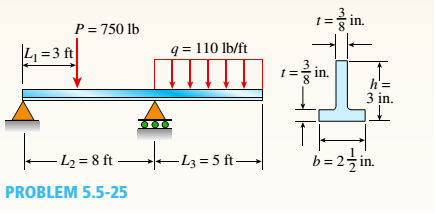
A beam with a T-section is supported and loaded as shown in the figure. The cross section has width b = 2 1/2 in., height c = 3 in., and thickness t = 3/8 in.
- Determine the maximum tensile and compressive stresses in the beam.
(a)
The maximum tensile stress.
The maximum compressive stress.
Explanation of Solution
Given information:
The uniform load is
The following figure shows the free body diagram of the beam.
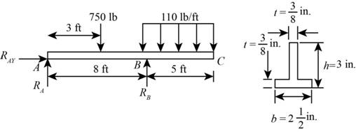
Figure-(1)
Write the expression for the distance of the neutral axis from the bottom layer.
Here, the width of the beam is
Write the expression for the distance of the neutral axis from the top layer.
Here, the distance of neutral axis from the top layer.
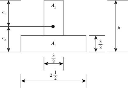
Figure-(2)
Write the expression for the moment of inertia.
Here, the moment of inertia is
Write the expression for the moment equilibrium about
Here, the reaction at point
Write the expression for the force equilibrium in vertical direction.
Here, the reaction at point
Write the expression for the maximum sagging moment at load
Here, the maximum sagging moment is
Write the expression for the maximum hogging moment at point
Here, the maximum hogging moment is
Write the expression for the maximum tensile stress at point
Here, the maximum tensile stress is
Write the expression for the maximum compressive stress at point
Here the maximum compressive stress is
Calculation:
Substitute
Substitute
Substitute
Substitute
Substitute
Substitute
Substitute
Substitute
Substitute
Conclusion:
The maximum tensile stress is
The maximum compressive stress is
(b)
The required depth of the beam.
Answer to Problem 5.5.25P
The required depth of the beam is
Explanation of Solution
Given Information:
The allowable stress in tension is
Write the expression for the maximum tensile stress at point
Write the expression for the distance of the neutral axis from the bottom layer.
Write the expression for the moment of inertia.
Calculation:
Substitute
Substitute
Substitute
. ......(XIII)
Substitute
Substitute
Conclusion:
The required depth of the beam is
Want to see more full solutions like this?
Chapter 5 Solutions
Bundle: Mechanics Of Materials, Loose-leaf Version, 9th + Mindtap Engineering, 2 Terms (12 Months) Printed Access Card


- Q.1) Block A is connected to block B by a pulley system as shown. The weights of blocks A and B are 100 lbs and 70 lbs, respectively. Assume negligible friction between the rope and all pulleys as well as between block B and the incline and neglect the mass of all pulleys and cables. Determine the angle 0 required to keep the system in equilibrium. (At least two FBDs must be drawn for full credit) B Ꮎ 000arrow_forwardpls solvearrow_forward+1. 0,63 fin r= 0.051 P The stepped rod in sketch is subjected to a tensile force that varies between 4000 and 7000 lb. The rod has a machined surface finish everywhere except the shoulder area, where a grinding operation has been performed to improve the fatigue resistance of the rod. Using a 99% probability of survival, determine the safety factor for infinite life if the rod is made of AISI 1080 steel, quenched and tempered at 800°c Use the Goodman line. Does the part fail at the fillet? Explainarrow_forward
- Solve this problem and show alll of the workarrow_forwardI need drawing solution,draw each one by one no Aiarrow_forwardQu. 17 Compute linear density values for [100] for silver (Ag). Express your answer in nm''. . Round off the answer to three significant figures. Qu. 18 Compute linear density value for [111] direction for silver (Ag). Express your answer in nm'. Round off the answer to three significant figures. Qu. 19 Compute planar density value for (100) plane for chromium (Cr). Express your answer in nm?. Round off the answer to two significant figures. Qu. 20 Compute planar density value for (110) plane for chromium (Cr). Express your answer in nm ≥ to four significant figures. show all work please in material engineeringarrow_forward
 Mechanics of Materials (MindTap Course List)Mechanical EngineeringISBN:9781337093347Author:Barry J. Goodno, James M. GerePublisher:Cengage Learning