
Bundle: Mechanics Of Materials, Loose-leaf Version, 9th + Mindtap Engineering, 2 Terms (12 Months) Printed Access Card
9th Edition
ISBN: 9781337594301
Author: Barry J. Goodno, James M. Gere
Publisher: Cengage Learning
expand_more
expand_more
format_list_bulleted
Videos
Textbook Question
Chapter 5, Problem 5.4.5P
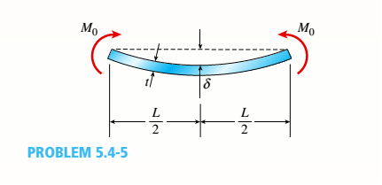
A thin strip of steel with a length of L =19 in. and thickness of t = 0,275 in. is bent by couples M0(see figure). The deflection at the midpoint of the strip (measured from a line joining its end points) is found to be 0.30 in.
- Determine the longitudinal normal strain ë at the top surface of the strip.
Expert Solution & Answer

Trending nowThis is a popular solution!

Students have asked these similar questions
I tried this problem and don't know what I did wrong or how else I could approach it can you please help me out?
Q3: An engine produce 750 kW power and uses gaseous C12H26 as a fuel
at 25 C; 200% theoretical air is used and air enters at 500 K. The products
of combustion leave at 800 K. The heat loss from the engine is 175 kW.
Determine the fuel consumption for complete combustion.
Qu 5 Determine the carburizing time necessary to achieve a carbon concentration of 0.30 wt% at a position 4 mm into an iron carbon alloy that initially contains 0.10 wt% C. The surface concentration is to be maintained at 0.90 wt% C, and the treatment is to be conducted at 1100°C. Use the data for the diffusion of
carbon into y-iron: Do = 2.3 x10⁻⁵ m2/s and Qd = 148,000 J/mol. Express your answer in hours to three significant figures.
show all work step by step problems formula material science
Chapter 5 Solutions
Bundle: Mechanics Of Materials, Loose-leaf Version, 9th + Mindtap Engineering, 2 Terms (12 Months) Printed Access Card
Ch. 5 - A steel wire with a diameter of d = 1/16 in. is...Ch. 5 - A copper wire having a diameter ofd = 4 mm is bent...Ch. 5 - A 4.75-in, outside diameter polyethylene pipe...Ch. 5 - A cantilever beam AB is loaded by a couple M0at...Ch. 5 - A thin strip of steel with a length of L =19 in....Ch. 5 - A bar of rectangular cross section is loaded and...Ch. 5 - A simply supported beam with a length L = 10 ft...Ch. 5 - A cantilever beam is subjected to a concentrated...Ch. 5 - A thin strip of hard copper (E = 16,000 ksi)...Ch. 5 - A steel wire (E = 200 GPa) of a diameter d = L25...
Ch. 5 - A thin, high-strength steel rule (E = 30 x 10ft...Ch. 5 - A simply supported wood beam AB with a span length...Ch. 5 - Beam ABC has simple supports at A and B and an...Ch. 5 - A simply supported beam is subjected to a in early...Ch. 5 - Each girder of the lift bridge (sec figure) is 180...Ch. 5 - A freight-car axle AS is loaded approximately as...Ch. 5 - A seesaw weighing 3 lb/ft of length is occupied by...Ch. 5 - During construction of a highway bridge, the main...Ch. 5 - The horizontal beam ABC of an oil-well pump has...Ch. 5 - A railroad tie (or sleeper) is subjected to two...Ch. 5 - A fiberglass pipe is lifted by a sling, as shown...Ch. 5 - A small dam of height h = 2.0 m is constructed of...Ch. 5 - Determine the maximum tensile stress (7, (due to...Ch. 5 - Determine the maximum bending stress emaxdue to...Ch. 5 - A simple beam A B of a span length L = 24 ft is...Ch. 5 - Determine the maximum tensile stress erand maximum...Ch. 5 - A cantilever beam A3, loaded by a uniform load and...Ch. 5 - A canti lever beam A B of a n isosceles t...Ch. 5 - A cantilever beam, a C12 x 30 section, is...Ch. 5 - A frame ABC travels horizontally with an...Ch. 5 - A beam ABC with an overhang from B to C supports a...Ch. 5 - A cantilever beam AB with a rectangular cross...Ch. 5 - A beam with a T-section is supported and loaded as...Ch. 5 - Consider the compound beam with segments AB and...Ch. 5 - A small dam of a height h = 6 ft is constructed of...Ch. 5 - A foot bridge on a hiking trail is constructed...Ch. 5 - A steel post (E=30×106) having thickness t = 1/8...Ch. 5 - Beam ABCDE has a moment release just right of...Ch. 5 - A simply supported wood beam having a span length...Ch. 5 - A simply supported beam (L = 4.5 m) must support...Ch. 5 - The cross section of a narrow-gage railway bridge...Ch. 5 - A fiberglass bracket A BCD with a solid circular...Ch. 5 - A cantilever beanie B is loaded by a uniform load...Ch. 5 - A simple beam of length L = 5 m carries a uniform...Ch. 5 - A simple beam AB is loaded as shown in the figure....Ch. 5 - A pontoon bridge (see figure) is constructed of...Ch. 5 - A floor system in a small building consists of...Ch. 5 - The wood joists supporting a plank Floor (see...Ch. 5 - A beam ABC with an overhang from B to C is...Ch. 5 - -12 A "trapeze bar" in a hospital room provides a...Ch. 5 - A two-axle carriage that is part of an over head...Ch. 5 - A cantilever beam AB with a circular cross section...Ch. 5 - A propped cantilever beam A BC (see figure) has a...Ch. 5 - A small balcony constructed of wood is supported...Ch. 5 - A beam having a cross section in the form of an un...Ch. 5 - A beam having a cross section in the form of a...Ch. 5 - Determine the ratios of the weights of four beams...Ch. 5 - Prob. 5.6.20PCh. 5 - A steel plate (called a cover ploie) having...Ch. 5 - A steel beam ABC is simply supported at A and...Ch. 5 - A retaining wall 6 ft high is constructed of...Ch. 5 - A retaining wall (Fig. a) is constructed using...Ch. 5 - A beam of square cross section (a = length of each...Ch. 5 - The cross section of a rectangular beam having a...Ch. 5 - A tapered cantilever beam A B of length L has...Ch. 5 - .2 A ligmio.irc ii supported by two vorlical beams...Ch. 5 - Prob. 5.7.3PCh. 5 - Prob. 5.7.4PCh. 5 - Prob. 5.7.5PCh. 5 - A cantilever beam AB with rectangular cross...Ch. 5 - A simple beam ABC having rectangular cross...Ch. 5 - A cantilever beam AB having rectangular cross...Ch. 5 - The shear stresses t in a rectangular beam arc...Ch. 5 - .2 Calculate the maximum shear stress tmaxand the...Ch. 5 - A simply supported wood beam is subjected to...Ch. 5 - A simply supported wood beam with overhang is...Ch. 5 - Two wood beams, each of rectangular cross section...Ch. 5 - A cantilever beam of length L = 2 m supports a...Ch. 5 - A steel beam of length L = 16 in. and...Ch. 5 - A beam of rectangular cross section (width/) and...Ch. 5 - A laminated wood beam on simple supports (figure...Ch. 5 - A laminated plastic beam of square cross section...Ch. 5 - A wood beam AB on simple supports with span length...Ch. 5 - A simply supported wood beam of rectangular cross...Ch. 5 - A square wood platform is 8 ft × 8 ft in area and...Ch. 5 - A wood beam ABC with simple supports at A and B...Ch. 5 - A wood pole with a solid circular cross section (d...Ch. 5 - A simple log bridge in a remote area consists of...Ch. 5 - A vertical pole consisting of a circular tube of...Ch. 5 - A circular pole is subjected to linearly varying...Ch. 5 - A sign for an automobile service station is...Ch. 5 - A steel pipe is subjected to a quadratic...Ch. 5 - -1 through 5.10-6 A wide-flange beam (see figure)...Ch. 5 - -1 through 5.10-6 A wide-flange beam (see figure)...Ch. 5 - -1 through 5.10-6 A wide-flange beam (see figure)...Ch. 5 - -1 through 5.10-6 A wide-flange beam (see figure)...Ch. 5 - -1 through 5.10-6 A wide-flange beam (see figure)...Ch. 5 - -1 through 5.10-6 A wide-flange beam (see figure)...Ch. 5 - A cantilever beam AB of length L = 6.5 ft supports...Ch. 5 - A bridge girder A B on a simple span of length L =...Ch. 5 - A simple beam with an overhang supports a uniform...Ch. 5 - A hollow steel box beam has the rectangular cross...Ch. 5 - A hollow aluminum box beam has the square cross...Ch. 5 - The T-beam shown in the figure has cross-sectional...Ch. 5 - Calculate the maximum shear stress tmax. in the...Ch. 5 - A prefabricated wood I-beam serving as a floor...Ch. 5 - A welded steel gird crhaving the erass section...Ch. 5 - A welded steel girder having the cross section...Ch. 5 - A wood box beam is constructed of two 260 mm × 50...Ch. 5 - A box beam is constructed of four wood boards as...Ch. 5 - Two wood box beams (beams A and B) have the same...Ch. 5 - A hollow wood beam with plywood webs has the...Ch. 5 - A beam of a T cross section is formed by nailing...Ch. 5 - The T-beam shown in the figure is fabricated by...Ch. 5 - A steel beam is built up from a W 410 × 85 wide...Ch. 5 - The three beams shown have approximately the same...Ch. 5 - Two W 310 × 74 Steel wide-flange beams are bolted...Ch. 5 - A pole is fixed at the base and is subjected to a...Ch. 5 - A solid circular pole is subjected to linearly...Ch. 5 - While drilling a hole with a brace and bit, you...Ch. 5 - An aluminum pole for a street light weighs 4600 N...Ch. 5 - A curved bar ABC having a circular axis (radius r...Ch. 5 - A rigid Trame ABC is formed by welding two steel...Ch. 5 - A palm tree weighing 1000 lb is inclined at an...Ch. 5 - A vertical pole of aluminum is fixed at the base...Ch. 5 - Because of foundation settlement, a circular tower...Ch. 5 - A steel bracket of solid circular cross section is...Ch. 5 - A cylindrical brick chimney of height H weighs w =...Ch. 5 - A flying but tress transmit s a load P = 25 kN,...Ch. 5 - A plain concrete wall (i.e., a wall with no steel...Ch. 5 - A circular post, a rectangular post, and a post of...Ch. 5 - Two cables, each carrying a tensile force P = 1200...Ch. 5 - Prob. 5.12.16PCh. 5 - A short column constructed of a W 12 × 35...Ch. 5 - A short column with a wide-flange shape is...Ch. 5 - A tension member constructed of an L inch angle...Ch. 5 - A short length of a C 200 × 17.1 channel is...Ch. 5 - The beams shown in the figure are subjected to...Ch. 5 - The beams shown in the figure are subjected to...Ch. 5 - A rectangular beam with semicircular notches, as...Ch. 5 - A rectangular beam with semicircular notches, as...Ch. 5 - A rectangular beam with notches and a hole (see...
Knowledge Booster


Learn more about
Need a deep-dive on the concept behind this application? Look no further. Learn more about this topic, mechanical-engineering and related others by exploring similar questions and additional content below.Similar questions
- (Read Question)arrow_forwardIn figure A, the homogeneous rod of constant cross section is attached to unyielding supports. In figure B, a homogeneous bar with a cross-sectional area of 600 mm2 is attached to rigid supports. The bar carries the axial loads P1 = 20 kN and P2 = 60 kN, as shown.1. In figure A, derive the expression that calculates the reaction R1 in terms of P, and the given dimensions.2. In figure B, calculate the reaction (kN) at A.3. In figure B, calculate the maximum axial stress (MPa) in the rod.arrow_forward(Read image)arrow_forward
- (Read Image)arrow_forwardM16x2 grade 8.8 bolts No. 25 C1- Q.2. The figure is a cross section of a grade 25 cast-iron pressure vessel. A total of N, M16x2.0 grade 8.8 bolts are to be used to resist a separating force of 160 kN. (a) Determine ks, km, and C. (b) Find the number of bolts required for a load factor of 2 where the bolts may be reused when the joint 19 mm is taken apart. (c) with the number of bolts obtained in (b), determine the realized load factor for overload, the yielding factor of safety, and the separation factor of safety. 19 mmarrow_forwardProblem4. The thin uniform disk of mass m = 1-kg and radius R = 0.1m spins about the bent shaft OG with the angular speed w2 = 20 rad/s. At the same time, the shaft rotates about the z-axis with the angular speed 001 = 10 rad/s. The angle between the bent portion of the shaft and the z-axis is ẞ = 35°. The mass of the shaft is negligible compared to the mass of the disk. a. Find the angular momentum of the disk with respect to point G, based on the axis orientation as shown. Include an MVD in your solution. b. Find the angular momentum of the disk with respect to point O, based on the axis orientation as shown. (Note: O is NOT the center of fixed-point rotation.) c. Find the kinetic energy of the assembly. z R R 002 2R x Answer: H = -0.046ĵ-0.040 kg-m²/sec Ho=-0.146-0.015 kg-m²/sec T 0.518 N-m =arrow_forward
- Problem 3. The assembly shown consists of a solid sphere of mass m and the uniform slender rod of the same mass, both of which are welded to the shaft. The assembly is rotating with angular velocity w at a particular moment. Find the angular momentum with respect to point O, in terms of the axes shown. Answer: Ñ。 = ½mc²wcosßsinßĵ + (}{mr²w + 2mb²w + ½ mc²wcos²ß) k 3 m r b 2 C لا marrow_forwardOnly question 2arrow_forwardOnly question 1arrow_forward
- Only question 3arrow_forwardI have Euler parameters that describe the orientation of N relative to Q, e = -0.7071*n3, e4 = 0.7071. I have Euler parameters that describe the orientation of U relative to N, e = -1/sqrt(3)*n1, e4 = sqrt(2/3). After using euler parameter rule of successive rotations, I get euler parameters that describe the orientation of U relative to Q, e = -0.4082*n1 - 0.4082*n2 - 0.5774*n3. I need euler parameters that describe the orientation of U relative to Q in vector basis of q instead of n. How do I get that?arrow_forwardDescribe at least 4 processes in engineering where control charts are (or should be) appliedarrow_forward
arrow_back_ios
SEE MORE QUESTIONS
arrow_forward_ios
Recommended textbooks for you
 Mechanics of Materials (MindTap Course List)Mechanical EngineeringISBN:9781337093347Author:Barry J. Goodno, James M. GerePublisher:Cengage Learning
Mechanics of Materials (MindTap Course List)
Mechanical Engineering
ISBN:9781337093347
Author:Barry J. Goodno, James M. Gere
Publisher:Cengage Learning
An Introduction to Stress and Strain; Author: The Efficient Engineer;https://www.youtube.com/watch?v=aQf6Q8t1FQE;License: Standard YouTube License, CC-BY