
International Edition---engineering Mechanics: Statics, 4th Edition
4th Edition
ISBN: 9781305501607
Author: Andrew Pytel And Jaan Kiusalaas
Publisher: CENGAGE L
expand_more
expand_more
format_list_bulleted
Concept explainers
Videos
Textbook Question
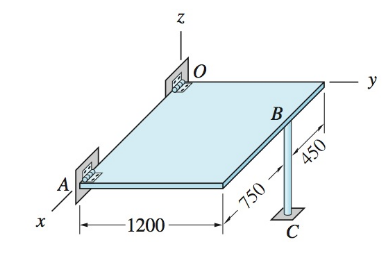
Chapter 5, Problem 5.21P
The homogeneous 20-kg door is held in the horizontal plane by a thrust hinge at O, a hinge at A, and the vertical prop BC. Determine all forces acting on the door.
Expert Solution & Answer

Trending nowThis is a popular solution!

Students have asked these similar questions
I don't want an AI solution please.
I don't want an AI solution please.
I don't want an AI solution please.
Chapter 5 Solutions
International Edition---engineering Mechanics: Statics, 4th Edition
Ch. 5 - Bar AB of negligible weight is supported by a...Ch. 5 - Draw the FBD for the bar described in Prob. 5.1 if...Ch. 5 - The space truss ABCD in the shape of a tetrahedron...Ch. 5 - Draw the FBD of the portion BCD of the space truss...Ch. 5 - The homogeneous plate of weight W is supported by...Ch. 5 - The bar ABCD of negligible weight is supported by...Ch. 5 - The shaft-pulley assembly is supported by the...Ch. 5 - The 60-lb homogeneous door is supported by hinges...Ch. 5 - Draw the FBD for bar BCD. The connections at A and...Ch. 5 - The homogeneous 360-lb plate with a rectangular...
Ch. 5 - The L-shaped rod, supported by slider bearings at...Ch. 5 - The homogeneous 240-lb bar is supported by a rough...Ch. 5 - In Sample Problem 5.4, determine the tension TAC...Ch. 5 - In Sample Problem 5.5, compute the tension TAD...Ch. 5 - In Sample Problem 5.5, determine Oy with one...Ch. 5 - Determine the tension TB in Sample Problem 5.6...Ch. 5 - Compute the tension TAE in Sample Problem 5.7...Ch. 5 - The 80-lb homogeneous plate is suspended from four...Ch. 5 - The three bars are welded together to form a rigid...Ch. 5 - The compound bar is supported by a thrust bearing...Ch. 5 - The homogeneous 20-kg door is held in the...Ch. 5 - The light boom AB is attached to the vertical wall...Ch. 5 - The homogeneous 80-kg sign is suspended from a...Ch. 5 - The bar ABC is supported by a ball-and-socket at A...Ch. 5 - Determine the forces in members PAE,PAF, and PBG...Ch. 5 - The figure shows the FBD of a portion of the space...Ch. 5 - Calculate all forces acting on the bar AB...Ch. 5 - Determine the forces in members AD, BD, and CD of...Ch. 5 - Find the tension in cable BE that supports the bar...Ch. 5 - For the structure in Prob. 5.9, determine the...Ch. 5 - Calculate the reaction at D for the structure...Ch. 5 - Calculate the reaction at D for the structure...Ch. 5 - Determine the tension in each of the three ropes...Ch. 5 - Using only one equilibrium equation, compute the...Ch. 5 - The homogeneous 25-kg bar AB is supported by a...Ch. 5 - The shaft AB is supported by a thrust bearing at A...Ch. 5 - The bar ABCD has a built-in support at A....Ch. 5 - The total weight of the L-shaped beam of constant...Ch. 5 - The bent rod of negligible weight is supported by...Ch. 5 - A 120-lb weight is attached to the cable that is...Ch. 5 - Calculate the force in cable CD and the reaction...Ch. 5 - The 350-lb homogeneous plate has the shape of an...Ch. 5 - The bent rod ABCD is supported by a...Ch. 5 - A hoist is formed by connecting bars BD and BE to...Ch. 5 - The crank arm OD of the winch is connected by a...Ch. 5 - The 80-lb homogeneous plate is supported by a...Ch. 5 - The frame is built into the wall at D and G. The...Ch. 5 - The bent bar of negligible weight is supported by...Ch. 5 - Determine the reactions at ball-and-socket joints...Ch. 5 - The 180-lb homogeneous bar is supported by a...Ch. 5 - The bent rod is supported by a ball-and-socket...Ch. 5 - Find the maximum load P that can be supported by...Ch. 5 - The vertical mast OA, which weighs 1.5 kN, is...Ch. 5 - The homogeneous bar AB weighs 50-lb. End B leans...Ch. 5 - The 500-kg crate is supported by the three cables....Ch. 5 - The uniform bars AB and BC each weigh 4 lb/ft....Ch. 5 - The rigid body of negligible weight is supported...Ch. 5 - The homogeneous 860-kg bar AB is supported by a...Ch. 5 - The triangular plate is supported by three...Ch. 5 - The connections at the ends of bars AB and BC arc...Ch. 5 - The bar AEB is supported by a ball-and-socket...Ch. 5 - The shaft is supported by a thrust bearing at A...
Knowledge Booster


Learn more about
Need a deep-dive on the concept behind this application? Look no further. Learn more about this topic, mechanical-engineering and related others by exploring similar questions and additional content below.Similar questions
- 1.7 Find the stress distribution in the beam shown in Fig. 1.23 using two beam elements. A. E. I constant M₂ T + FIGURE 1.23 A fixed-pinned beam subjected to a momentarrow_forward42 PART 1 Introduction A. E. I constant FIGURE 1.22 A fixed-pinned beam. 1.6 Find the stress distribution in the beam shown in Fig. 1.22 using two beam elements.arrow_forward1.4 Using a one-beam element idealization, find the stress distribution under a load of P for the uniform cantilever beam shown in Fig. 1.20. A, E, I constant L FIGURE 1.20 A uniform cantilever beamarrow_forward
- Mechanical engineering,FBD required.arrow_forwardSolve this problem and show all of the workarrow_forwardPlease Please use MATLAB with codes and graph. Recreate the following four Figures of the textbook using MATLAB and the appropriate parameters. Comment on your observations for each Figure. List all of the parameters that you have used. The figure is attached below.arrow_forward
- Please only step 6 (last time I asked it was cut off at that point)arrow_forwardPlease Please use a MATLAB with codes and grap. Recreate the following four Figures of the textbook using MATLAB and the appropriate parameters. Comment on your observations for each Figure. List all of the parameters that you have used. The figure attached below.arrow_forwardI REPEAT!!!!! I NEED HANDDRAWING!!!!! NOT A USELESS EXPLANATION!!!! I REPEAT SUBMIT A HANDDRAWING IF YOU CANNOT UNDERSTAND THIS SKIP IT ! I need the real handdrawing complete it by adding these : Pneumatic Valves Each linear actuator must be controlled by a directional control valve (DCV) (e.g., 5/2 or 4/2 valve). The bi-directional motor requires a reversible valve to change rotation direction. Pressure Regulators & Air Supply Include two pressure regulators as per the assignment requirement. Show the main compressed air supply line connecting all components. Limit Switches & Safety Features Attach limit switches to each actuator to detect positions. Implement a two-handed push-button safety system to control actuator movement. Connections Between Components Draw air supply lines linking the compressor, valves, and actuators. Clearly label all inputs and outputs for better understanding.arrow_forward
- I need the real handdrawing complete it by adding these : Pneumatic Valves Each linear actuator must be controlled by a directional control valve (DCV) (e.g., 5/2 or 4/2 valve). The bi-directional motor requires a reversible valve to change rotation direction. Pressure Regulators & Air Supply Include two pressure regulators as per the assignment requirement. Show the main compressed air supply line connecting all components. Limit Switches & Safety Features Attach limit switches to each actuator to detect positions. Implement a two-handed push-button safety system to control actuator movement. Connections Between Components Draw air supply lines linking the compressor, valves, and actuators. Clearly label all inputs and outputs for better understanding.arrow_forwardAn elastic bar of the length L and cross section area A is rigidly attached to the ceiling of a room, and it supports a mass M. Due to the acceleration of gravity g the rod deforms vertically. The deformation of the rod is measured by the vertical displacement u(x) governed by the following equations: dx (σ(x)) + b(x) = 0 PDE σ(x) = Edx du Hooke's law (1) b(x) = gp= body force per unit volume where E is the constant Young's modulus, p is the density, and σ(x) the axial stress in the rod. g * I u(x) L 2arrow_forwardAn elastic bar of the length L and cross section area A is rigidly attached to the ceiling of a room, and it supports a mass M. Due to the acceleration of gravity g the rod deforms vertically. The deformation of the rod is measured by the vertical displacement u(x) governed by the following equations: dx (σ(x)) + b(x) = 0 PDE σ(x) = Edx du Hooke's law (1) b(x) = gp= body force per unit volume where E is the constant Young's modulus, p is the density, and σ(x) the axial stress in the rod. g * I u(x) L 2arrow_forward
arrow_back_ios
SEE MORE QUESTIONS
arrow_forward_ios
Recommended textbooks for you
 International Edition---engineering Mechanics: St...Mechanical EngineeringISBN:9781305501607Author:Andrew Pytel And Jaan KiusalaasPublisher:CENGAGE L
International Edition---engineering Mechanics: St...
Mechanical Engineering
ISBN:9781305501607
Author:Andrew Pytel And Jaan Kiusalaas
Publisher:CENGAGE L
Solids: Lesson 53 - Slope and Deflection of Beams Intro; Author: Jeff Hanson;https://www.youtube.com/watch?v=I7lTq68JRmY;License: Standard YouTube License, CC-BY