
Concept explainers
Videos
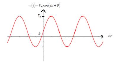
Consider the plot of the sinusoidal voltage
- Stretches the sinusoidal curve vertically.
Which statement best describes
b. Increasing the frequency f?
c. Decreasing
d. Decreasing the angular frequency w?
e. Increasing the period?
(a)
Change in sinusoidal voltage graph if peak amplitude is increased.
Answer to Problem 5.1P
Increasing the peak amplitude stretches the sinusoidal curve vertically.
Option (1).
Explanation of Solution
Given information:
Given sinusoidal voltage is
Calculation:
Graph of sinusoidal voltage is
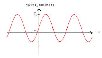
From the graph, it is noted thatif peak amplitude Vm is increased, it stretches the sinusoidal curve vertically.
(b)
Change in sinusoidal voltage graph if frequency is increased.
Answer to Problem 5.1P
Increasing the frequency compresses the sinusoidal curve horizontally.
Option (4).
Explanation of Solution
Given information:
Given sinusoidal voltage is
Calculation:
Graph of sinusoidal voltage is

From the graph, it is noted that if the frequency is increased,the time period is reduced so that it compresses the sinusoidal curve horizontally.
(c)
Change in sinusoidal voltage graph if phase angle (theta) is decreased.
Answer to Problem 5.1P
Decreasing the phase angle (theta) translates the sinusoidal curve to the right.
Option (5).
Explanation of Solution
Given information:
Given sinusoidal voltage is
Calculation:
Graph of sinusoidal voltage is

From the graph, it is noted that if the phase angle (theta) is decreased, it translates the sinusoidal curve to the right.
(d)
Change in sinusoidal voltage graph if the angular frequency is decreased.
Answer to Problem 5.1P
Decreasing the angular frequency stretches the sinusoidal voltage graph horizontally.
Option (3).
Explanation of Solution
Given information:
Given sinusoidal voltage is
Calculation:
Graph of sinusoidal voltage is
From the graph, it is noted that if the angular frequency is decreased, it increases the time period of the curve,which means it stretches sinusoidal horizontally.
(e)
Change in sinusoidal voltage graph if the time period is increased.
Answer to Problem 5.1P
Increasing the time period stretches the sinusoidal voltage graph horizontally.
Option (3).
Explanation of Solution
Given information:
Given sinusoidal voltage is
Calculation:
Graph of sinusoidal voltage is

From the graph, it is noted that if time period is increased, it stretches the sinusoidal voltage graph horizontally.
Want to see more full solutions like this?
Chapter 5 Solutions
Electrical Engineering: Principles & Applications, Student Value Edition Plus Mastering Engineering with Pearson eText -- Access Card Package (7th Edition)
Additional Engineering Textbook Solutions
Elementary Surveying: An Introduction To Geomatics (15th Edition)
Computer Science: An Overview (13th Edition) (What's New in Computer Science)
Degarmo's Materials And Processes In Manufacturing
Mechanics of Materials (10th Edition)
Introduction To Programming Using Visual Basic (11th Edition)
Java: An Introduction to Problem Solving and Programming (8th Edition)


- R is 12 kΩ . Find the Thevenin equivalent resistance.arrow_forwardAssuming an ideal op-amp, design an inverting amplifier with a gain of 25 dB having the largest possible input resistance under the constraint of having to use resistors no larger than 90 kΩ. What's the input resist?arrow_forwardI need help with this problem and an explanation of the solution for the image described below. (Introduction to Signals and Systems)arrow_forward
- I hope the solution is on paper and not artificial intelligence. The subject is control systemarrow_forwardI hope the solution is on paper and not artificial intelligence.arrow_forwardVs R1 R2 ww ww 21x R3 Define the Thevenin equivalent of the above circuit where R1= 10 52, R2= 30 S2, R3 = 30 12, Vs = 70 V. VThevenin Number V RThevenin = Number Ωarrow_forward
- R1 ww + R3 15+ www R2 R4 ww With the circuit diagram shown above and the values of the circuit elements listed below, find i1, 12, v1, and v2. Is = 10A, R1 = 7 ohms, R2 = 9 ohms, R3 = 7 ohms, R4 = 8 ohms (a) i1 = Number A (b) 12 = Number A (c) v1 = Number V (d) v2 = Number Varrow_forward15 ww 22 R2 ли i4 1+ V4 R1 ww R3 Solve for current i4 using superposition where R1 = 902, R2 = 36052, R3 = 360 V, and 15 = 5 A. 27052, V4 = i4 due to voltage source (V4) alone: Number A i4 due to current source (15) alone: Number A i4 = Numberarrow_forwardPV Array Va DC/DC Converter Control Circuit ис V R Fig. 2. Principle of using DC/DC converter to implement electronic load [2] 4.5 1.5 -0.5 SEPIC Converters in SOM 0 0.2 0.4 0.6 0.8 Time SEPIC Converters in SOM M 0 0.2 0.4 0.6 0.8 Time Current I-V Curve (a) 8888888 P-V Curve 0 20 40 60 80 Voltage 0 20 40 60 Voltage 80 (b) Fig. 3. Experimental results of I-V and P-V curves [2]arrow_forward
 Introductory Circuit Analysis (13th Edition)Electrical EngineeringISBN:9780133923605Author:Robert L. BoylestadPublisher:PEARSON
 Delmar's Standard Textbook Of ElectricityElectrical EngineeringISBN:9781337900348Author:Stephen L. HermanPublisher:Cengage Learning
 Programmable Logic ControllersElectrical EngineeringISBN:9780073373843Author:Frank D. PetruzellaPublisher:McGraw-Hill Education
 Fundamentals of Electric CircuitsElectrical EngineeringISBN:9780078028229Author:Charles K Alexander, Matthew SadikuPublisher:McGraw-Hill Education
 Electric Circuits. (11th Edition)Electrical EngineeringISBN:9780134746968Author:James W. Nilsson, Susan RiedelPublisher:PEARSON
 Engineering ElectromagneticsElectrical EngineeringISBN:9780078028151Author:Hayt, William H. (william Hart), Jr, BUCK, John A.Publisher:Mcgraw-hill Education,