
Electrical Engineering: Principles & Applications, Student Value Edition Plus Mastering Engineering with Pearson eText -- Access Card Package (7th Edition)
7th Edition
ISBN: 9780134702193
Author: Allan R. Hambley
Publisher: PEARSON
expand_more
expand_more
format_list_bulleted
Concept explainers
Videos
Textbook Question
Chapter 5, Problem 5.81P
Two loads. A and B, are connected in parallel across a 1-kV-rms 60-Hz line, as shown in Figure P5.81. Load A consumes 10 kW with a 90 percent lagging power facto. Load B has an apparent power of 15 ICVA with an 80 percent lagging power factor. Find the power, reactive power, and apparent power delivered by the source. What is the power factor seen by the source?
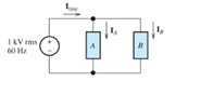
Figure P5.81
Expert Solution & Answer
Want to see the full answer?
Check out a sample textbook solution
Students have asked these similar questions
a
step
Oster D
Ramp
ess??
Lead-Lag compensater
100
S(S+50
Bafter compensator
KP
K=Y
Telo
Phase
Lead
Phase
Lag
100
SCS+5
Zoe
9=013
P=5
Z-65
T=10
K-032
b=10
T=100
S+312
Sta2
Lead
S
T=1
k=0.2
How can I calculate (ess) from A and B &
"Please, the answer must be documented from a
book, experience, or accurate information without
using artificial intelligence."
Write an Arduino program that flash ON the 4-LED's by using
two switches according to the following scenarios:
1. when S₁=1 then L3, L4 are ON.
2. when S₁=0 then L1,L2 are ON.
3. when S2=1 then L2,L4 are ON.
4. when S2-0 then L₁,L3 are ON.
140
Both circuit do it multisim okk don't use guidelines will dislike okk
Chapter 5 Solutions
Electrical Engineering: Principles & Applications, Student Value Edition Plus Mastering Engineering with Pearson eText -- Access Card Package (7th Edition)
Ch. 5 - Consider the plot of the sinusoidal voltage...Ch. 5 - Repeat Problem P5.3 for v(t) = 50 sin (500t+120) .Ch. 5 - A sinusoidal voltage v(t) has an rms value of 20...Ch. 5 - A current i(t)=10cos(2000t) flows through a 100...Ch. 5 - We have a voltage v(t)=1000sin(500t) across a 500...Ch. 5 - Calculate the rms value of the half-wave rectified...Ch. 5 - We have v1(t)=10cos(t+30) . The current i1(t)has...Ch. 5 - Solve for the mesh currents shown in Figure P5.55.Ch. 5 - Two loads. A and B, are connected in parallel...
Knowledge Booster


Learn more about
Need a deep-dive on the concept behind this application? Look no further. Learn more about this topic, electrical-engineering and related others by exploring similar questions and additional content below.Similar questions
- "Please, the answer must be documented from a book, experience, or accurate information without using artificial intelligence." Write an Arduino program to read the status of two push buttons connected to pins 2&3 respectively and flash ON two LED's connected to pins 12&13 respectively according to the following scenario: If pin 2 is HIGH let LED 12 flash with delay of 400ms, and if pin 3 HIGH, let LED 13 flash ON with delay of 300ms.arrow_forward"Based on a source, book, or expertise in the specialized field, I need a solution to the question." Write an Arduino program code that controls the intensity of each LED (Ascending and descending) connected to pins {3, 5, 6, 9, 10, 11} successively at an array method) an interval one of one second. (Hint usearrow_forward"Based on a source, book, or expertise in the specialized field, I need a solution to the question." Write an Arduino program to control water tank levels, The 1st Tank level is monitored by ultrasonic sensor No.1, connected to pin Ao on the Arduino board and it's linked to a valve via port 7 to regulate the valve's opening and closing. Similarly, 2nd tank is monitored by ultrasonic sensor No.2, connected to pin A1, and linked to a valve through port 8. Follow the rules in the Table below to control valve and motor activation via port 13 with a 500 ms delay: TRIYAH UN Water level Tank Tank 1<500 (Threshold) Tank 2<300 Tank 1==500 Tank 2<300 Tank 1<500 Tank 2==300 Tank 1=500 Tank 2=300 Motor ON ON SON OFF Valve 1 ON OFF ON OFF Valve 2 ON ON OFF OFFarrow_forward
- "Based on a source, book, or expertise in the specialized field, I need a solution to the question." 1985 Write an Arduino program to flash flash three LED's connected to pins (7, 9 & 11) respectively as shown in figure below: (Note: T₁-T3-5s & T₂=3s) LED₁ (pin 7) LED2 (pin 9) LED3 (pin 11) T₁ T2 T3 1406arrow_forward"Based on a source, book, or expertise in the specialized field, I need a solution to the question." Write an Arduino programming code that activates eight LEDs connected to pins 0 to 7 successively with an interval of 1 second when switch S₁ connected to pins 8 is turned ON, and all LEDs are activated when switch S₂ connected to pins 9 is turned off. (Hint: use array method).arrow_forwardDetermine X(w) for the given function shown in Figure (1) by applying the differentiation property of the Fourier Transform. 1 x(t) Figure (1) -1 1 2arrow_forward
- 5. Determine an expression for vo as a function of vs in the circuit shown below. Assume the operational amplifier is ideal (10 pts) 162 + + 212 10052} -j 100-52 Noarrow_forward4. A 120 volt rms voltage source supplies 20 Amps rms to a load. The load requires 2,078 watts. What is the reactive power (Vars) and the power factor of the load. Assume the load is inductive. (15pts)arrow_forward6. Determine the rms value of the voltage cyclical waveform shown below. (15 pts) Zv N 시 ما Msec 8arrow_forward
arrow_back_ios
SEE MORE QUESTIONS
arrow_forward_ios
Recommended textbooks for you
 Power System Analysis and Design (MindTap Course ...Electrical EngineeringISBN:9781305632134Author:J. Duncan Glover, Thomas Overbye, Mulukutla S. SarmaPublisher:Cengage Learning
Power System Analysis and Design (MindTap Course ...
Electrical Engineering
ISBN:9781305632134
Author:J. Duncan Glover, Thomas Overbye, Mulukutla S. Sarma
Publisher:Cengage Learning
What is the Difference Between Single Phase and Three Phase???; Author: Electrician U;https://www.youtube.com/watch?v=FEydcr4wJw0;License: Standard Youtube License