
Concept explainers
Videos
a)
Show that the maximum compressive stresses are in the ratio 4:5:7:9.
a)
Explanation of Solution
Given information:
The load act on the point of the bars is P.
Calculation:
At the point A:
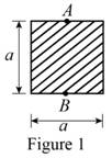
Show the cross-sectional diagram of the square bar as in Figure 1.
Here,
Refer to Figure 1.
The maximum compressive stress of the square bar
Here, e is the eccentricity of the load and
The cross-sectional area of the square bar
The eccentricity of the load (e) is
The distance between the centroid from extreme fibre
The moment of inertia
Calculate the maximum compressive stress of the square bar
Substitute
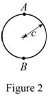
Show the cross-sectional diagram of the circular bar as in Figure 2.
Here,
Refer to Figure 2.
The maximum compressive stress of the circular bar
The cross-sectional area of the circular bar
The eccentricity of the load (e) is
The distance between the centroid from extreme fibre
The moment of inertia
Calculate the maximum compressive stress of the circular bar
Substitute
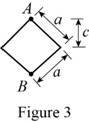
Show the cross-sectional diagram of the diamond shape bar as in Figure 3.
Here,
Refer to Figure 3.
The maximum compressive stress of the diamond shape bar
The cross-sectional area of the diamond shape bar
The eccentricity of the load (e) is
The distance between the centroid from extreme fibre
The moment of inertia
Calculate the maximum compressive stress of the diamond shape bar
Substitute
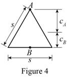
Show the cross-sectional diagram of the triangular bar as in Figure 4.
Here,
Refer to Figure 4.
The maximum compressive stress of the triangular bar
The cross-sectional area of the triangular bar
The distance between the centroid from extreme fibre
The eccentricity of the load (e) is
The moment of inertia
Calculate the maximum compressive stress of the triangular bar
Substitute
Calculate the maximum compressive stresses are in the ratio:
Substitute
The four bars shown have the same cross-sectional area.
Hence the maximum compressive stresses are in the ratio 4:5:7:9 is proved.
b)
Show that the maximum tensile stresses are in the ratio 2:3:5:3.
b)
Explanation of Solution
Given information:
The load act on the point of the bars is P.
Calculation:
At the point B:
Refer to Figure 1.
The maximum tensile stress of the square bar
Here, the e is the eccentricity of the load and
The cross-sectional area of the square bar
The eccentricity of the load (e) is
The distance between the centroid from extreme fibre
The moment of inertia
Calculate the maximum tensile stress of the square bar
Substitute
Refer to Figure 2.
The maximum tensile stress of the circular bar
The cross-sectional area of the circular bar
The eccentricity of the load (e) is
The distance between the centroid from extreme fibre
The moment of inertia
Calculate the maximum tensile stress of the circular bar
Substitute
Refer to Figure 3.
The maximum tensile stress of the diamond shape bar
The cross-sectional area of the diamond shape bar
The eccentricity of the load (e) is
The distance between the centroid from extreme fibre
The moment of inertia
Calculate the maximum tensile stress of the diamond shape bar
Substitute
Refer to Figure 4.
The maximum tensile stress of the triangular bar
The cross-sectional area of the triangular bar
The distance between the centroid from extreme fibre
The eccentricity of the load (e) is
The moment of inertia
Calculate the maximum tensile stress of the triangular bar
Substitute
Calculate the maximum tensile stresses are in the ratio:
Substitute
The four bars shown have the same cross-sectional area.
Hence the maximum tensile stresses are in the ratio 2:3:5:3 is proved.
Want to see more full solutions like this?
Chapter 4 Solutions
EBK MECHANICS OF MATERIALS


- What is the procedure to replace the input bellows?(I found this question on the internet and was wondering what the correct answer is out of interest) Remove tubing, old bellows and flapper assembly, install new bellows, connect tubing, install flapper assembly, then calibrate the positioner.Remove tubing, old bellows and cam, install new bellows, connect tubing, install cam, then calibrate the positioner.C. Remove tubing and old bellows, align the quadrant beam, install new bellows and connect tubing, then calibrate the positioner.D. Remove tubing and old bellows, install new bellows and connect tubing, align the quadrant beam, then calibrate the positioner.arrow_forwardGiven the following information: (I found this question on the internet and was wondering what the correct answer is) Firing rate demand = 20% Fuel air ratio = 2:1 Fuel flow = 20% Minimum air flow setting = 5% What is the set point for the air flow controller? 5%B. 10%C. 25%D. 40%arrow_forward. Where is a dew point analyzer installed to measure instrument air?(I found this question on the internet and am wondering what the correct answer is) A. AB. BC. CD. Darrow_forward
- The piston at the bottom of the stroke is 0% open. Which adjustment will change the zero setting to 5% open? ( I found this sample question on the internet and was wondering what the correct answer is out of interest) A.Slide component 2 towards the pivotB. Slide component 2 away from the pivot.C. Increase spring tension using adjustment 1.D. Decrease spring tension using adjustment 1.arrow_forward(read image) (Answer: vA = 4.57 ft/sec)arrow_forward(read image) (answer: αAB = 14.38 rad/s2 CW)arrow_forward
 Elements Of ElectromagneticsMechanical EngineeringISBN:9780190698614Author:Sadiku, Matthew N. O.Publisher:Oxford University Press
 Mechanics of Materials (10th Edition)Mechanical EngineeringISBN:9780134319650Author:Russell C. HibbelerPublisher:PEARSON
 Thermodynamics: An Engineering ApproachMechanical EngineeringISBN:9781259822674Author:Yunus A. Cengel Dr., Michael A. BolesPublisher:McGraw-Hill Education
 Control Systems EngineeringMechanical EngineeringISBN:9781118170519Author:Norman S. NisePublisher:WILEY
 Mechanics of Materials (MindTap Course List)Mechanical EngineeringISBN:9781337093347Author:Barry J. Goodno, James M. GerePublisher:Cengage Learning
 Engineering Mechanics: StaticsMechanical EngineeringISBN:9781118807330Author:James L. Meriam, L. G. Kraige, J. N. BoltonPublisher:WILEY