
MOD MASTERING STATICS + DYNAMICS >I<
14th Edition
ISBN: 9781323327067
Author: HIBBELER
Publisher: PEARSON C
expand_more
expand_more
format_list_bulleted
Videos
Textbook Question
Chapter 4.4, Problem 5P
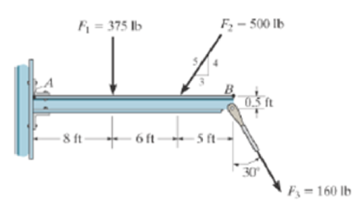
Determine the moment about point B of each of the three forces acting on the beam.
Probs. 4–4/5
Expert Solution & Answer
Want to see the full answer?
Check out a sample textbook solution
Students have asked these similar questions
M
× Your answer is incorrect.
(Manometer) Determine the angle 0 of the inclined tube shown in figure below if the pressure at A is 1 psi greater than that at B.
1ft
SG=0.61
十
A
Ꮎ
1ft
SG=1.0
8.8 ft
0 =
Hi
15.20
deg
Air
I don't know how to solve this
Chapter 4 Solutions
MOD MASTERING STATICS + DYNAMICS >I<
Ch. 4.4 - In each case, determine the moment of the force...Ch. 4.4 - In each case, set up the determinant to find the...Ch. 4.4 - Determine the moment of the force about point O.Ch. 4.4 - Determine the moment of the force about point O.Ch. 4.4 - Determine the moment of the force about point O.Ch. 4.4 - Determine the moment of the force about point O....Ch. 4.4 - Determine the moment of the force about point O.Ch. 4.4 - Determine the moment of the force about point O.Ch. 4.4 - Determine the resultant moment produced by the...Ch. 4.4 - Determine the resultant moment produced by the...
Ch. 4.4 - Determine the resultant moment produced by the...Ch. 4.4 - Determine the moment of force F about point O....Ch. 4.4 - Prob. 11FPCh. 4.4 - Prob. 12FPCh. 4.4 - Prob. 1PCh. 4.4 - Prove the triple scalar product identity A (B C)...Ch. 4.4 - Prob. 3PCh. 4.4 - Prob. 4PCh. 4.4 - Determine the moment about point B of each of the...Ch. 4.4 - The crowbar is subjected to a vertical force of P...Ch. 4.4 - Determine the moment of each of the three forces...Ch. 4.4 - Determine the moment of each of the three forces...Ch. 4.4 - Determine the moment of each force about the bolt...Ch. 4.4 - If FB = 30 lb and FC = 45 lb, determine the...Ch. 4.4 - Prob. 11PCh. 4.4 - The towline exerts a force of P = 6 kN at the end...Ch. 4.4 - Prob. 13PCh. 4.4 - The 20-N horizontal force acts on the handle of...Ch. 4.4 - Two men exert forces of F = 80 lb and P = 50 lb on...Ch. 4.4 - Prob. 16PCh. 4.4 - Prob. 17PCh. 4.4 - The tongs are used to grip the ends of the...Ch. 4.4 - Prob. 19PCh. 4.4 - The handle of the hammer is subjected to the force...Ch. 4.4 - In order to pull out the nail at B, the force F...Ch. 4.4 - Old clocks were constructed using a fusee B to...Ch. 4.4 - The tower crane is used to hoist the 2-Mg load...Ch. 4.4 - The tower crane is used to hoist a 2-Mg load...Ch. 4.4 - If the 1500-lb boom AB, the 200-lb cage BCD, and...Ch. 4.4 - If the 1500-lb boom AB, the 200-lb cage BCD, and...Ch. 4.4 - Determine the moment of the force F about point O....Ch. 4.4 - Determine the moment of the force F about point P....Ch. 4.4 - The force F = {400i 100j 700k} lb acts at the...Ch. 4.4 - The force F = {400i 100j 700k} lb acts at the end...Ch. 4.4 - Determine the moment of the force F about point P....Ch. 4.4 - The pipe assembly is subjected to the force of F =...Ch. 4.4 - The pipe assembly is subjected to the force of F =...Ch. 4.4 - Determine the moment of the force of F = 600 N...Ch. 4.4 - Determine the smallest force F that must be...Ch. 4.4 - Determine the coordinate direction angles , , of...Ch. 4.4 - Determine the moment of force F about point O. The...Ch. 4.4 - Determine the moment of the force F about the door...Ch. 4.4 - Determine the moment of the force F about the door...Ch. 4.4 - Determine the smallest force F that must be...Ch. 4.4 - Prob. 41PCh. 4.4 - A 20-N horizontal force is applied perpendicular...Ch. 4.4 - Prob. 43PCh. 4.4 - The pipe assembly is subjected to the 80-N force....Ch. 4.4 - Prob. 45PCh. 4.4 - Prob. 46PCh. 4.4 - Prob. 47PCh. 4.4 - Prob. 48PCh. 4.4 - Prob. 49PCh. 4.4 - Prob. 50PCh. 4.4 - Using a ring collar, the 75-N force can act in the...Ch. 4.5 - In each case, determine the resultant moment of...Ch. 4.5 - Prob. 4PPCh. 4.5 - Prob. 13FPCh. 4.5 - Prob. 14FPCh. 4.5 - Determine the magnitude of the moment of the 200-N...Ch. 4.5 - Determine the magnitude of the moment of the force...Ch. 4.5 - Prob. 17FPCh. 4.5 - Determine the moment of force F about the x, the...Ch. 4.5 - The lug nut on the wheel of the automobile is to...Ch. 4.5 - Solve Prob. 4-52 if the cheater pipe AB is slipped...Ch. 4.5 - The A-frame is being hoisted into an upright...Ch. 4.5 - Prob. 55PCh. 4.5 - Determine the magnitude of the moments of the...Ch. 4.5 - Determine the moment of this force F about an axis...Ch. 4.5 - Prob. 58PCh. 4.5 - Prob. 59PCh. 4.5 - Prob. 60PCh. 4.5 - Determine the magnitude of the moment of the force...Ch. 4.5 - Determine the magnitude of the moment of the force...Ch. 4.5 - Determine the magnitude of the moment of the force...Ch. 4.5 - A horizontal force of F = {50i} N is applied...Ch. 4.5 - Prob. 65PCh. 4.5 - Prob. 66PCh. 4.6 - Determine the resultant couple moment acting on...Ch. 4.6 - Determine the resultant couple moment acting on...Ch. 4.6 - Prob. 21FPCh. 4.6 - Determine the couple moment acting on the beam.Ch. 4.6 - Determine the resultant couple moment acting on...Ch. 4.6 - Determine the couple moment acting on the pipe...Ch. 4.6 - Prob. 67PCh. 4.6 - Prob. 68PCh. 4.6 - If the resultant couple of the three couples...Ch. 4.6 - Two couples act on the beam. If F = 125 lb,...Ch. 4.6 - Two couples act on the beam. Determine the...Ch. 4.6 - Determine the magnitude of the couple forces F so...Ch. 4.6 - Prob. 73PCh. 4.6 - Prob. 74PCh. 4.6 - Prob. 75PCh. 4.6 - Determine the magnitude of F so that the resultant...Ch. 4.6 - Prob. 77PCh. 4.6 - Prob. 78PCh. 4.6 - Two couples act on the frame. If the resultant...Ch. 4.6 - Prob. 80PCh. 4.6 - Two couples act on the frame. If d = 4 ft,...Ch. 4.6 - Prob. 82PCh. 4.6 - If M1 = 180 lb ft, M2 = 90 lb ft, and M3 = 120...Ch. 4.6 - Prob. 84PCh. 4.6 - The gears are subjected to the couple moments...Ch. 4.6 - Determine the required magnitude of the couple...Ch. 4.6 - Determine the resultant couple moment of the two...Ch. 4.6 - Express the moment of the couple acting on the...Ch. 4.6 - In order to turn over the frame, a couple moment...Ch. 4.6 - Express the moment of the couple acting on the...Ch. 4.6 - If the couple moment acting on the pipe has a...Ch. 4.6 - If F = 80 N, determine the magnitude and...Ch. 4.6 - If the magnitude of the couple moment acting on...Ch. 4.6 - Express the moment of the couple acting on the rod...Ch. 4.6 - If F1 = 100 N, F2 = 120 N, and F3 = 80 N,...Ch. 4.6 - Prob. 96PCh. 4.7 - In each case, determine the x and y components of...Ch. 4.7 - F-25. Replace the leading system by an equivalent...Ch. 4.7 - F-26. Replace the loading system by an equivalent...Ch. 4.7 - Prob. 27FPCh. 4.7 - Prob. 28FPCh. 4.7 - Prob. 29FPCh. 4.7 - F-30. Replace the loading system by an equivalent...Ch. 4.7 - Replace the force system by an equivalent...Ch. 4.7 - Prob. 98PCh. 4.7 - Prob. 99PCh. 4.7 - Prob. 100PCh. 4.7 - Replace the loading system acting on the beam by...Ch. 4.7 - Prob. 102PCh. 4.7 - Prob. 103PCh. 4.7 - Prob. 104PCh. 4.7 - Replace the force system acting on the frame by an...Ch. 4.7 - Prob. 106PCh. 4.7 - Prob. 107PCh. 4.7 - Replace the force system by an equivalent...Ch. 4.7 - Prob. 109PCh. 4.7 - Prob. 110PCh. 4.7 - Prob. 111PCh. 4.7 - Prob. 112PCh. 4.8 - In each case, determine the x and y components of...Ch. 4.8 - Prob. 7PPCh. 4.8 - Replace the loading system by an equivalent...Ch. 4.8 - Prob. 32FPCh. 4.8 - Prob. 33FPCh. 4.8 - Prob. 34FPCh. 4.8 - Prob. 35FPCh. 4.8 - Prob. 36FPCh. 4.8 - Prob. 113PCh. 4.8 - Prob. 114PCh. 4.8 - Prob. 115PCh. 4.8 - Prob. 116PCh. 4.8 - Replace the loading acting on the beam by a single...Ch. 4.8 - Prob. 118PCh. 4.8 - Prob. 119PCh. 4.8 - Prob. 120PCh. 4.8 - Prob. 121PCh. 4.8 - Prob. 122PCh. 4.8 - Prob. 123PCh. 4.8 - Prob. 124PCh. 4.8 - Prob. 125PCh. 4.8 - Replace the force and couple system acting on the...Ch. 4.8 - If FA = 7 kN and FB = 5 kN, represent the force...Ch. 4.8 - Determine the magnitudes of FA and FB so that the...Ch. 4.8 - Prob. 129PCh. 4.8 - Prob. 130PCh. 4.8 - Prob. 131PCh. 4.8 - If FA= 40 kN and FB = 35 kN, determine the...Ch. 4.8 - If the resultant force is required to act at the...Ch. 4.8 - Prob. 134PCh. 4.8 - Replace the force system by a wrench and specify...Ch. 4.8 - Prob. 136PCh. 4.8 - Replace the three forces acting on the plate by a...Ch. 4.9 - Determine the resultant force and specify where it...Ch. 4.9 - Prob. 38FPCh. 4.9 - Prob. 39FPCh. 4.9 - Determine the resultant force and specify where it...Ch. 4.9 - Prob. 41FPCh. 4.9 - Prob. 42FPCh. 4.9 - Replace the loading by an equivalent resultant...Ch. 4.9 - Replace the distributed loading with an equivalent...Ch. 4.9 - Prob. 140PCh. 4.9 - Prob. 141PCh. 4.9 - Replace the distributed loading by an equivalent...Ch. 4.9 - Replace this loading by an equivalent resultant...Ch. 4.9 - The distribution of soil loading on the bottom of...Ch. 4.9 - Replace the loading by an equivalent resultant...Ch. 4.9 - Replace the distributed loading by an equivalent...Ch. 4.9 - Prob. 147PCh. 4.9 - Prob. 148PCh. 4.9 - If the soil exerts a trapezoidal distribution of...Ch. 4.9 - Prob. 150PCh. 4.9 - Prob. 151PCh. 4.9 - Prob. 152PCh. 4.9 - Replace the leading by a single resultant force,...Ch. 4.9 - Prob. 154PCh. 4.9 - Replace the distributed loading by an equivalent...Ch. 4.9 - Prob. 156PCh. 4.9 - Prob. 157PCh. 4.9 - Prob. 158PCh. 4.9 - The distributed load acts on the shaft as shown....Ch. 4.9 - Replace the distributed loading with an equivalent...Ch. 4.9 - Prob. 161PCh. 4.9 - Prob. 162PCh. 4.9 - Prob. 1RPCh. 4.9 - Replace the force F having a magnitude of F = 50...Ch. 4.9 - Prob. 3RPCh. 4.9 - Prob. 4RPCh. 4.9 - Prob. 5RPCh. 4.9 - Prob. 6RPCh. 4.9 - Prob. 7RPCh. 4.9 - Prob. 8RP
Knowledge Booster


Learn more about
Need a deep-dive on the concept behind this application? Look no further. Learn more about this topic, mechanical-engineering and related others by exploring similar questions and additional content below.Similar questions
- 1. The maximum and minimum stresses as well as the shear stress seen subjected the piece in plane A-A. Assume it is a cylinder with a diameter of 12.7mm 2. Draw the Mohr circle for the stress state using software. 3. Selection of the material for the prosthesis, which must be analyzed from the point of safety and cost view.arrow_forwardFirst, define the coordinate system XY with its origin at O2 and X-axis passing through O4 asshown above, then based on the provided steps Perform coordinate transformation from XY to xy to get the trajectory of point P. Show all the steps and calcualtionsarrow_forwardI don't know how to solve thisarrow_forward
- Question 2 (40 Points) Consider the following double pendulum-like system with links ₁ and 12. The angles 0 and & could have angular velocities ėêk and êk, respectively, where ②k is a unit vector that points out of the page and is perpendicular to x and y. They could also have angular accelerations Ök and êk. The angle is defined relative to the angle 0. The link 12 is a spring and can extend or compress at a rate of 12. It can also have a rate of extension or compression Ï2. li y êr1 êe 12 χ 3 еф er2 ده لج 1) Express the velocity of the mass in terms of the unit vectors ê0, êr1, êø, and êr2, and any extension/contraction of the links (e.g.,. i; and Ï¿) (12 Points) 2) Express the acceleration of the mass in terms of the unit vectors ê¤, ê×1, êp, and êÃ2, and any extension/contraction of the links (e.g.,. İ; and Ï¿) (12 Points) 3) Express the velocity of the mass in terms of unit vectors î and ĵ that point in the x and y directions, respectively. Also include the appropriate,…arrow_forwardprovide step by step solutions for angles teta 3 and teta 4 by the vector loopmethod. Show work in: vector loop, vector equations, solution procedure.arrow_forward(Manometer) A tank is constructed of a series of cylinders having diameters of 0.35, 0.30, and 0.20 m as shown in the figure below. The tank contains oil, water, and glycerin and a mercury manometer is attached to the bottom as illustrated. Calculate the manometer reading, h. 0.11 m + SAE 30 Oil 0.13 m + Water 0.10 m Glycerin + 0.10 m Mercury h = marrow_forward
- P = A piston having a cross-sectional area of 0.40 m² is located in a cylinder containing water as shown in the figure below. An open U-tube manometer is connected to the cylinder as shown. For h₁ = 83 mm and h = 111 mm what is the value of the applied force, P, acting on the piston? The weight of the piston is negligible. Hi 5597.97 N P Piston Water Mercuryarrow_forwardStudent Name: Student Id: College of Applied Engineering Al-Muzahmiyah Branch Statics (AGE 1330) Section-1483 Quiz-2 Time: 20 minutes Date: 16/02/2025 Q.1. A swinging door that weighs w=400.0N is supported by hinges A and B so that the door can swing about a vertical' axis passing through the hinges (as shown in below figure). The door has a width of b=1.00m and the door slab has a uniform mass density. The hinges are placed symmetrically at the door's edge in such a way that the door's weight is evenly distributed between them. The hinges are separated by distance a=2.00m. Find the forces on the hinges when the door rests half-open. Draw Free body diagram also. [5 marks] [CLO 1.2] Mool b ర a 2.0 m B 1.0 marrow_forwardFor the walking-beam mechanism shown in Figure 3, find and plot the x and y coordinates of the position of the coupler point P for one complete revolution of the crank O2A. Use the coordinate system shown in Figure 3. Hint: Calculate them first with respect to the ground link 0204 and then transform them into the global XY coordinate system. y -1.75 Ꮎ Ꮎ 4 = 2.33 0242.22 L4 x AP = 3.06 L2 = 1.0 W2 31° B 03 L3 = 2.06 P 1 8 5 .06 6 7 P'arrow_forward
- The link lengths, gear ratio (2), phase angle (Ø), and the value of 02 for some geared five bar linkages are defined in Table 2. The linkage configuration and terminology are shown in Figure 2. For the rows assigned, find all possible solutions for angles 03 and 04 by the vector loop method. Show your work in details: vector loop, vector equations, solution procedure. Table 2 Row Link 1 Link 2 Link 3 Link 4 Link 5 λ Φ Ө a 6 1 7 9 4 2 30° 60° P y 4 YA B b R4 R3 YA A Gear ratio: a 02 d 05 r5 R5 R2 Phase angle: = 0₂-202 R1 05 02 r2 Figure 2. 04 Xarrow_forwardProblem 4 A .025 lb bullet C is fired at end B of the 15-lb slender bar AB. The bar is initially at rest, and the initial velocity of the bullet is 1500 ft/s as shown. Assuming that the bullet becomes embedded in the bar, find (a) the angular velocity @2 of the bar immediately after impact, and (b) the percentage loss of kinetic energy as a result of the impact. (c) After the impact, does the bar swing up 90° and reach the horizontal? If it does, what is its angular velocity at this point? Answers: (a). @2=1.6 rad/s; (b). 99.6% loss = (c). Ah2 0.212 ft. The bar does not reach horizontal. y X 4 ft 15 lb V₁ 1500 ft/s 0.025 lb C 30°7 B Aarrow_forwardsubject: combustion please include complete solution, no rounding off, with diagram/explanation etc. In a joule cycle, intake of the compressor is 40,000 cfm at 0.3 psig and 90 deg F. The compression ratio is 6.0 and the inlet temperature at the turbine portion is 1900R while at the exit, it is 15 psi. Calculate for the back work ratio in percent.arrow_forward
arrow_back_ios
SEE MORE QUESTIONS
arrow_forward_ios
Recommended textbooks for you
 International Edition---engineering Mechanics: St...Mechanical EngineeringISBN:9781305501607Author:Andrew Pytel And Jaan KiusalaasPublisher:CENGAGE L
International Edition---engineering Mechanics: St...
Mechanical Engineering
ISBN:9781305501607
Author:Andrew Pytel And Jaan Kiusalaas
Publisher:CENGAGE L
How to balance a see saw using moments example problem; Author: Engineer4Free;https://www.youtube.com/watch?v=d7tX37j-iHU;License: Standard Youtube License