
MOD MASTERING STATICS + DYNAMICS >I<
14th Edition
ISBN: 9781323327067
Author: HIBBELER
Publisher: PEARSON C
expand_more
expand_more
format_list_bulleted
Concept explainers
Videos
Textbook Question
Chapter 4.4, Problem 18P
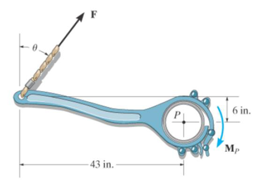
The tongs are used to grip the ends of the drilling pipe P. Determine the torque (moment) MP that the applied force F = 150 lb exerts on the pipe about point P as a function of θ. Plot this moment MP versus θ for 0 ≤ θ ≤ 90°.
Expert Solution & Answer
Want to see the full answer?
Check out a sample textbook solution
Students have asked these similar questions
Assume a Space Launch System (Figure 1(a)) that is approximated as a cantilever undamped single degree of freedom (SDOF) system with a mass at its free end (Figure 1(b)). The cantilever is assumed to be massless. Assume a wind load that is approximated with a concentrated harmonic forcing function p(t) = posin(ωt) acting on the mass. The known properties of the SDOF and the applied forcing function are given below. • Mass of SDOF: m =120 kip/g • Acceleration of gravity: g = 386 in/sec2 • Bending sectional stiffness of SDOF: EI = 1015 lbf×in2 • Height of SDOF: h = 2000 inches • Amplitude of forcing function: po = 6 kip • Forcing frequency: f = 8 Hz Figure 1: Single-degree-of-freedom system in Problem 1. Please compute the following considering the steady-state response of the SDOF system. Do not consider the transient response unless it is explicitly stated in the question. (a) The natural circular frequency and the natural period of the SDOF. (10 points) (b) The maximum displacement of…
Please solve
13 * √(2675.16)² + (63.72 + 2255,03)² = 175x106
can you explain the process for
getting d seperate thank you
If the 300-kg drum has a center of mass at point G,
determine the horizontal and vertical components of
force acting at pin A and the reactions on the smooth
pads C and D. The grip at B on member DAB resists both
horizontal and vertical components of force at the rim of
the drum.
P
60 mm;
60 mm:
600 mm
A
E
30°
B
C
390 mm
100 mm
D
G
Chapter 4 Solutions
MOD MASTERING STATICS + DYNAMICS >I<
Ch. 4.4 - In each case, determine the moment of the force...Ch. 4.4 - In each case, set up the determinant to find the...Ch. 4.4 - Determine the moment of the force about point O.Ch. 4.4 - Determine the moment of the force about point O.Ch. 4.4 - Determine the moment of the force about point O.Ch. 4.4 - Determine the moment of the force about point O....Ch. 4.4 - Determine the moment of the force about point O.Ch. 4.4 - Determine the moment of the force about point O.Ch. 4.4 - Determine the resultant moment produced by the...Ch. 4.4 - Determine the resultant moment produced by the...
Ch. 4.4 - Determine the resultant moment produced by the...Ch. 4.4 - Determine the moment of force F about point O....Ch. 4.4 - Prob. 11FPCh. 4.4 - Prob. 12FPCh. 4.4 - Prob. 1PCh. 4.4 - Prove the triple scalar product identity A (B C)...Ch. 4.4 - Prob. 3PCh. 4.4 - Prob. 4PCh. 4.4 - Determine the moment about point B of each of the...Ch. 4.4 - The crowbar is subjected to a vertical force of P...Ch. 4.4 - Determine the moment of each of the three forces...Ch. 4.4 - Determine the moment of each of the three forces...Ch. 4.4 - Determine the moment of each force about the bolt...Ch. 4.4 - If FB = 30 lb and FC = 45 lb, determine the...Ch. 4.4 - Prob. 11PCh. 4.4 - The towline exerts a force of P = 6 kN at the end...Ch. 4.4 - Prob. 13PCh. 4.4 - The 20-N horizontal force acts on the handle of...Ch. 4.4 - Two men exert forces of F = 80 lb and P = 50 lb on...Ch. 4.4 - Prob. 16PCh. 4.4 - Prob. 17PCh. 4.4 - The tongs are used to grip the ends of the...Ch. 4.4 - Prob. 19PCh. 4.4 - The handle of the hammer is subjected to the force...Ch. 4.4 - In order to pull out the nail at B, the force F...Ch. 4.4 - Old clocks were constructed using a fusee B to...Ch. 4.4 - The tower crane is used to hoist the 2-Mg load...Ch. 4.4 - The tower crane is used to hoist a 2-Mg load...Ch. 4.4 - If the 1500-lb boom AB, the 200-lb cage BCD, and...Ch. 4.4 - If the 1500-lb boom AB, the 200-lb cage BCD, and...Ch. 4.4 - Determine the moment of the force F about point O....Ch. 4.4 - Determine the moment of the force F about point P....Ch. 4.4 - The force F = {400i 100j 700k} lb acts at the...Ch. 4.4 - The force F = {400i 100j 700k} lb acts at the end...Ch. 4.4 - Determine the moment of the force F about point P....Ch. 4.4 - The pipe assembly is subjected to the force of F =...Ch. 4.4 - The pipe assembly is subjected to the force of F =...Ch. 4.4 - Determine the moment of the force of F = 600 N...Ch. 4.4 - Determine the smallest force F that must be...Ch. 4.4 - Determine the coordinate direction angles , , of...Ch. 4.4 - Determine the moment of force F about point O. The...Ch. 4.4 - Determine the moment of the force F about the door...Ch. 4.4 - Determine the moment of the force F about the door...Ch. 4.4 - Determine the smallest force F that must be...Ch. 4.4 - Prob. 41PCh. 4.4 - A 20-N horizontal force is applied perpendicular...Ch. 4.4 - Prob. 43PCh. 4.4 - The pipe assembly is subjected to the 80-N force....Ch. 4.4 - Prob. 45PCh. 4.4 - Prob. 46PCh. 4.4 - Prob. 47PCh. 4.4 - Prob. 48PCh. 4.4 - Prob. 49PCh. 4.4 - Prob. 50PCh. 4.4 - Using a ring collar, the 75-N force can act in the...Ch. 4.5 - In each case, determine the resultant moment of...Ch. 4.5 - Prob. 4PPCh. 4.5 - Prob. 13FPCh. 4.5 - Prob. 14FPCh. 4.5 - Determine the magnitude of the moment of the 200-N...Ch. 4.5 - Determine the magnitude of the moment of the force...Ch. 4.5 - Prob. 17FPCh. 4.5 - Determine the moment of force F about the x, the...Ch. 4.5 - The lug nut on the wheel of the automobile is to...Ch. 4.5 - Solve Prob. 4-52 if the cheater pipe AB is slipped...Ch. 4.5 - The A-frame is being hoisted into an upright...Ch. 4.5 - Prob. 55PCh. 4.5 - Determine the magnitude of the moments of the...Ch. 4.5 - Determine the moment of this force F about an axis...Ch. 4.5 - Prob. 58PCh. 4.5 - Prob. 59PCh. 4.5 - Prob. 60PCh. 4.5 - Determine the magnitude of the moment of the force...Ch. 4.5 - Determine the magnitude of the moment of the force...Ch. 4.5 - Determine the magnitude of the moment of the force...Ch. 4.5 - A horizontal force of F = {50i} N is applied...Ch. 4.5 - Prob. 65PCh. 4.5 - Prob. 66PCh. 4.6 - Determine the resultant couple moment acting on...Ch. 4.6 - Determine the resultant couple moment acting on...Ch. 4.6 - Prob. 21FPCh. 4.6 - Determine the couple moment acting on the beam.Ch. 4.6 - Determine the resultant couple moment acting on...Ch. 4.6 - Determine the couple moment acting on the pipe...Ch. 4.6 - Prob. 67PCh. 4.6 - Prob. 68PCh. 4.6 - If the resultant couple of the three couples...Ch. 4.6 - Two couples act on the beam. If F = 125 lb,...Ch. 4.6 - Two couples act on the beam. Determine the...Ch. 4.6 - Determine the magnitude of the couple forces F so...Ch. 4.6 - Prob. 73PCh. 4.6 - Prob. 74PCh. 4.6 - Prob. 75PCh. 4.6 - Determine the magnitude of F so that the resultant...Ch. 4.6 - Prob. 77PCh. 4.6 - Prob. 78PCh. 4.6 - Two couples act on the frame. If the resultant...Ch. 4.6 - Prob. 80PCh. 4.6 - Two couples act on the frame. If d = 4 ft,...Ch. 4.6 - Prob. 82PCh. 4.6 - If M1 = 180 lb ft, M2 = 90 lb ft, and M3 = 120...Ch. 4.6 - Prob. 84PCh. 4.6 - The gears are subjected to the couple moments...Ch. 4.6 - Determine the required magnitude of the couple...Ch. 4.6 - Determine the resultant couple moment of the two...Ch. 4.6 - Express the moment of the couple acting on the...Ch. 4.6 - In order to turn over the frame, a couple moment...Ch. 4.6 - Express the moment of the couple acting on the...Ch. 4.6 - If the couple moment acting on the pipe has a...Ch. 4.6 - If F = 80 N, determine the magnitude and...Ch. 4.6 - If the magnitude of the couple moment acting on...Ch. 4.6 - Express the moment of the couple acting on the rod...Ch. 4.6 - If F1 = 100 N, F2 = 120 N, and F3 = 80 N,...Ch. 4.6 - Prob. 96PCh. 4.7 - In each case, determine the x and y components of...Ch. 4.7 - F-25. Replace the leading system by an equivalent...Ch. 4.7 - F-26. Replace the loading system by an equivalent...Ch. 4.7 - Prob. 27FPCh. 4.7 - Prob. 28FPCh. 4.7 - Prob. 29FPCh. 4.7 - F-30. Replace the loading system by an equivalent...Ch. 4.7 - Replace the force system by an equivalent...Ch. 4.7 - Prob. 98PCh. 4.7 - Prob. 99PCh. 4.7 - Prob. 100PCh. 4.7 - Replace the loading system acting on the beam by...Ch. 4.7 - Prob. 102PCh. 4.7 - Prob. 103PCh. 4.7 - Prob. 104PCh. 4.7 - Replace the force system acting on the frame by an...Ch. 4.7 - Prob. 106PCh. 4.7 - Prob. 107PCh. 4.7 - Replace the force system by an equivalent...Ch. 4.7 - Prob. 109PCh. 4.7 - Prob. 110PCh. 4.7 - Prob. 111PCh. 4.7 - Prob. 112PCh. 4.8 - In each case, determine the x and y components of...Ch. 4.8 - Prob. 7PPCh. 4.8 - Replace the loading system by an equivalent...Ch. 4.8 - Prob. 32FPCh. 4.8 - Prob. 33FPCh. 4.8 - Prob. 34FPCh. 4.8 - Prob. 35FPCh. 4.8 - Prob. 36FPCh. 4.8 - Prob. 113PCh. 4.8 - Prob. 114PCh. 4.8 - Prob. 115PCh. 4.8 - Prob. 116PCh. 4.8 - Replace the loading acting on the beam by a single...Ch. 4.8 - Prob. 118PCh. 4.8 - Prob. 119PCh. 4.8 - Prob. 120PCh. 4.8 - Prob. 121PCh. 4.8 - Prob. 122PCh. 4.8 - Prob. 123PCh. 4.8 - Prob. 124PCh. 4.8 - Prob. 125PCh. 4.8 - Replace the force and couple system acting on the...Ch. 4.8 - If FA = 7 kN and FB = 5 kN, represent the force...Ch. 4.8 - Determine the magnitudes of FA and FB so that the...Ch. 4.8 - Prob. 129PCh. 4.8 - Prob. 130PCh. 4.8 - Prob. 131PCh. 4.8 - If FA= 40 kN and FB = 35 kN, determine the...Ch. 4.8 - If the resultant force is required to act at the...Ch. 4.8 - Prob. 134PCh. 4.8 - Replace the force system by a wrench and specify...Ch. 4.8 - Prob. 136PCh. 4.8 - Replace the three forces acting on the plate by a...Ch. 4.9 - Determine the resultant force and specify where it...Ch. 4.9 - Prob. 38FPCh. 4.9 - Prob. 39FPCh. 4.9 - Determine the resultant force and specify where it...Ch. 4.9 - Prob. 41FPCh. 4.9 - Prob. 42FPCh. 4.9 - Replace the loading by an equivalent resultant...Ch. 4.9 - Replace the distributed loading with an equivalent...Ch. 4.9 - Prob. 140PCh. 4.9 - Prob. 141PCh. 4.9 - Replace the distributed loading by an equivalent...Ch. 4.9 - Replace this loading by an equivalent resultant...Ch. 4.9 - The distribution of soil loading on the bottom of...Ch. 4.9 - Replace the loading by an equivalent resultant...Ch. 4.9 - Replace the distributed loading by an equivalent...Ch. 4.9 - Prob. 147PCh. 4.9 - Prob. 148PCh. 4.9 - If the soil exerts a trapezoidal distribution of...Ch. 4.9 - Prob. 150PCh. 4.9 - Prob. 151PCh. 4.9 - Prob. 152PCh. 4.9 - Replace the leading by a single resultant force,...Ch. 4.9 - Prob. 154PCh. 4.9 - Replace the distributed loading by an equivalent...Ch. 4.9 - Prob. 156PCh. 4.9 - Prob. 157PCh. 4.9 - Prob. 158PCh. 4.9 - The distributed load acts on the shaft as shown....Ch. 4.9 - Replace the distributed loading with an equivalent...Ch. 4.9 - Prob. 161PCh. 4.9 - Prob. 162PCh. 4.9 - Prob. 1RPCh. 4.9 - Replace the force F having a magnitude of F = 50...Ch. 4.9 - Prob. 3RPCh. 4.9 - Prob. 4RPCh. 4.9 - Prob. 5RPCh. 4.9 - Prob. 6RPCh. 4.9 - Prob. 7RPCh. 4.9 - Prob. 8RP
Knowledge Booster


Learn more about
Need a deep-dive on the concept behind this application? Look no further. Learn more about this topic, mechanical-engineering and related others by exploring similar questions and additional content below.Similar questions
- The design of the gear-and-shaft system shown requires that steel shafts of the same diameter be used for both AB and CD. It is further required that the angle D through which end D of shaft CD rotates not exceed 1.5°. Knowing that G = 77.2 GPa, determine the required diameter of the shafts. 40 mm 400 mm 100 mm 600 mm T-1000 N-m Darrow_forwardAssume a Space Launch System (Figure 1(a)) that is approximated as a cantilever undamped single degree of freedom (SDOF) system with a mass at its free end (Figure 1(b)). The cantilever is assumed to be massless. Assume a wind load that is approximated with a concentrated harmonic forcing function p(t) = posin(ωt) acting on the mass. The known properties of the SDOF and the applied forcing function are given below. • Mass of SDOF: m =120 kip/g • Acceleration of gravity: g = 386 in/sec2 • Bending sectional stiffness of SDOF: EI = 1015 lbf×in2 • Height of SDOF: h = 2000 inches • Amplitude of forcing function: po = 6 kip • Forcing frequency: f = 8 Hzarrow_forward13.44 The end of a cylindrical liquid cryogenic propellant tank in free space is to be protected from external (solar) radiation by placing a thin metallic shield in front of the tank. Assume the view factor Fts between the tank and the shield is unity; all surfaces are diffuse and gray, and the surroundings are at 0 K. Tank T₁ Shield, T T₁ = 100 K E1 Solar irradiation Gs ε₁ = ε₂ = 0.05 ε₁ = 0.10 Gs = 1250 W/m² E2 Find the temperature of the shield T, and the heat flux (W/m²) to the end of the tank.arrow_forward
- question 664 thank youarrow_forward13.38 Consider the attic of a home located in a hot climate. The floor of the attic is characterized by a width of L₁ = 8 m while the roof makes an angle of 0 = 30° from the horizontal direction, as shown in the schematic. The homeowner wishes to reduce the heat load to the home by adhering bright aluminum foil (ε = 0.07) onto the surfaces of the attic space. Prior to installation of the foil, the surfaces are of emissivity & = 0.90. Attic A2, 82, T2 0 = 30° A1, E1, T₁ 土 L₁ = 8 m (a) Consider installation on the bottom of the attic roof only. Determine the ratio of the radiation heat transfer after to before the installation of the foil. (b) Determine the ratio of the radiation heat transfer after to before installation if the foil is installed only on the top of the attic floor. (c) Determine the ratio of the radiation heat transfer if the foil is installed on both the roof bottom and the floor top.arrow_forward13.1 Determine F2 and F2 for the following configura- tions using the reciprocity theorem and other basic shape factor relations. Do not use tables or charts. (a) Small sphere of area A, under a concentric hemi- sphere of area A₂ = 3A₁ A₂ A1 (a) (b) Long duct. Also, what is F₁₂? A₂ Αν (b) (c) Long inclined plates (point B is directly above the center of A₁) B 100 mm A₂ - 220 mm (c) (d) Long cylinder lying on infinite plane + A₁ Az (d) (e) Hemisphere-disk arrangement -A₂, hemisphere, diameter D A₂ A₁, disk, diameter D/2 (e) (f) Long, open channel 1 m AA₂ 2 m (f) (g) Long cylinders with A₁ = 4A₁. Also, what is F₁₂? -D₁ A1 -A₂ -D2 (e) (h) Long, square rod in a long cylinder. Also, what is F22? w=D/5 18 A₁ -A2 (h) -Darrow_forward
- 13.9 Determine the shape factor, F12, for the rectangles shown. 6 m 1 3 m 6 m 1 m 2 6 m 1 0.5 m 2 1 m (a) Perpendicular rectangles without a common edge. -1 m. (b) Parallel rectangles of unequal areas.arrow_forwardI keep getting the wrong answer i have gotten 6519.87 and 319.71arrow_forwardthank you for previous answer I apologize if the acceleration was unclear it is underlined now along with values in tablesarrow_forward
- ११११११११ TABLE Much 160,000kg Croll 0,005 CD Ap Par ng При nchs 0.15 5m² 1.2kg/m³ 0.98 0.9 0,98 0,9 0,88 IF 20 10 to add The train is going to make several stops along its journey. It will be important for the train to accelerate quickdy to get back up to speed. In order to get Tesla Model S motors until we get the combined The Forque and power needed we are goins bined power and forque needed to accelerate from 0 to 324 km/hr in less than 5 Minutes. Tesla Prated 270 kW Tesla Trated Twheel ng Jaxle 440 NM 20 8.5kgm² 0.45M a) What is the minimum whole number of Tesla Motors required to achieve accelerate the train from 0 to 324 km/hr in less than 5 Nnutes? Seperate the acceleration into constant torque and constant power 0. b) How long does it take the train to accelerate from 0 to 324 km/hr with the number of Tesla motors from part a? c) Using Matlab plot the relocity profile as a function of time, Is this a constant acceleration profile? Barrow_forwardExample find f(t)? -4s F(s)= (s² + 4)²arrow_forwarddraw a kinematic diagramarrow_forward
arrow_back_ios
SEE MORE QUESTIONS
arrow_forward_ios
Recommended textbooks for you
 Elements Of ElectromagneticsMechanical EngineeringISBN:9780190698614Author:Sadiku, Matthew N. O.Publisher:Oxford University Press
 Mechanics of Materials (10th Edition)Mechanical EngineeringISBN:9780134319650Author:Russell C. HibbelerPublisher:PEARSON
 Thermodynamics: An Engineering ApproachMechanical EngineeringISBN:9781259822674Author:Yunus A. Cengel Dr., Michael A. BolesPublisher:McGraw-Hill Education
 Control Systems EngineeringMechanical EngineeringISBN:9781118170519Author:Norman S. NisePublisher:WILEY
 Mechanics of Materials (MindTap Course List)Mechanical EngineeringISBN:9781337093347Author:Barry J. Goodno, James M. GerePublisher:Cengage Learning
 Engineering Mechanics: StaticsMechanical EngineeringISBN:9781118807330Author:James L. Meriam, L. G. Kraige, J. N. BoltonPublisher:WILEY
Elements Of Electromagnetics
Mechanical Engineering
ISBN:9780190698614
Author:Sadiku, Matthew N. O.
Publisher:Oxford University Press
Mechanics of Materials (10th Edition)
Mechanical Engineering
ISBN:9780134319650
Author:Russell C. Hibbeler
Publisher:PEARSON
Thermodynamics: An Engineering Approach
Mechanical Engineering
ISBN:9781259822674
Author:Yunus A. Cengel Dr., Michael A. Boles
Publisher:McGraw-Hill Education
Control Systems Engineering
Mechanical Engineering
ISBN:9781118170519
Author:Norman S. Nise
Publisher:WILEY
Mechanics of Materials (MindTap Course List)
Mechanical Engineering
ISBN:9781337093347
Author:Barry J. Goodno, James M. Gere
Publisher:Cengage Learning
Engineering Mechanics: Statics
Mechanical Engineering
ISBN:9781118807330
Author:James L. Meriam, L. G. Kraige, J. N. Bolton
Publisher:WILEY
Introduction To Engg Mechanics - Newton's Laws of motion - Kinetics - Kinematics; Author: EzEd Channel;https://www.youtube.com/watch?v=ksmsp9OzAsI;License: Standard YouTube License, CC-BY