
Vector Mechanics for Engineers: Statics and Dynamics
11th Edition
ISBN: 9780073398242
Author: Ferdinand P. Beer, E. Russell Johnston Jr., David Mazurek, Phillip J. Cornwell, Brian Self
Publisher: McGraw-Hill Education
expand_more
expand_more
format_list_bulleted
Videos
Textbook Question
Chapter 4.3, Problem 4.111P
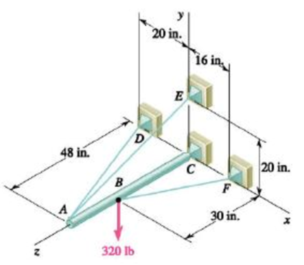
PROBLEM 4.111
A 48-in. boom is held by a ball-and-socket joint at C and by two cables BF and DAE; cable DAE passes around a frictionless pulley at A. For the loading shown, determine the tension in each cable and the reaction at C.
Expert Solution & Answer
Want to see the full answer?
Check out a sample textbook solution
Students have asked these similar questions
Repeat Problem 28, except using a shaft that is rotatingand transmitting a torque of 150 N * m from the left bearing to the middle of the shaft. Also, there is a profile keyseat at the middle under the load.
(I want to understand this problem)
Prob 2.
The material distorts into the dashed position
shown. Determine the average normal strains &x, Ey
and the shear strain Yxy at A, and the average
normal strain along line BE.
50 mm
B
200 mm
15 mm
30 mm
D
ΕΙ
50 mm
x
A
150 mm
F
Prob 3.
The triangular plate is fixed at its base, and its apex
A is given a horizontal displacement of 5 mm.
Determine the shear strain, Yxy, at A.
Prob 4.
The triangular plate is fixed at its base, and its apex
A is given a horizontal displacement of 5 mm.
Determine the average normal strain & along the x
axis.
Prob 5.
The triangular plate is fixed at its base, and its apex
A is given a horizontal displacement of 5 mm.
Determine the average normal strain &x along the x'
axis.
x'
45°
800 mm
45°
45%
800 mm
5 mm
Chapter 4 Solutions
Vector Mechanics for Engineers: Statics and Dynamics
Ch. 4.1 - Two crates, each of mass 350 kg, are placed as...Ch. 4.1 - A lever AB is hinged at C and attached to a...Ch. 4.1 - A light rod AD is supported by frictionless pegs...Ch. 4.1 - A tension of 20 N is maintained in a tape as it...Ch. 4.1 - A gardener uses a 60 N wheelbarrow to transport a...Ch. 4.1 - The gardener of Prob. 4.1 wishes to transport a...Ch. 4.1 - A 2100-lb tractor is used to lift 900 lb of grave....Ch. 4.1 - For the beam and loading shown, determine (a) the...Ch. 4.1 - A load of lumber of weight W = 25 kN is being...Ch. 4.1 - A load of lumber of weight W = 25 kN is being...
Ch. 4.1 - Prob. 4.7PCh. 4.1 - Prob. 4.8PCh. 4.1 - Three loads are applied as shown to a light beam...Ch. 4.1 - Prob. 4.10PCh. 4.1 - Prob. 4.11PCh. 4.1 - For the beam of Sample Prob. 4.2, determine the...Ch. 4.1 - The maximum allowable value of each of the...Ch. 4.1 - For the beam and loading shown, determine the...Ch. 4.1 - 4.15 Two links AB and DE are connected by a bell...Ch. 4.1 - Prob. 4.16PCh. 4.1 - 4.17 The required tension in cable AB is 200 lb....Ch. 4.1 - Prob. 4.18PCh. 4.1 - The bracket BCD is hinged at C and attached to a...Ch. 4.1 - The ladder AB, of length L and weight W, can be...Ch. 4.1 - 4.21 The 40-ft boom AB weighs 2 kips; the distance...Ch. 4.1 - A lever AB is hinged at C and attached to a...Ch. 4.1 - 4.23 and 4.24 For each of the plates and loadings...Ch. 4.1 - Prob. 4.24PCh. 4.1 - A rod AB, hinged at A and attached at B to cable...Ch. 4.1 - Prob. 4.26PCh. 4.1 - Prob. 4.27PCh. 4.1 - Determine the reactions at A and C when (a) = 0,...Ch. 4.1 - Prob. 4.29PCh. 4.1 - Prob. 4.30PCh. 4.1 - Neglecting friction, determine the tension in...Ch. 4.1 - Fig. P4.31 and P4.32 4.32 Neglecting friction,...Ch. 4.1 - PROBLEM 4.33 A force P of magnitude 90 lb is...Ch. 4.1 - PROBLEM 4.34 Solve Problem 4,33 for a = 6 in,...Ch. 4.1 - Prob. 4.35PCh. 4.1 - PROBLEM 4.36 A light bar AD is suspended from a...Ch. 4.1 - Prob. 4.37PCh. 4.1 - Prob. 4.38PCh. 4.1 - Prob. 4.39PCh. 4.1 - Prob. 4.40PCh. 4.1 - Prob. 4.41PCh. 4.1 - Prob. 4.42PCh. 4.1 - The rig shown consists of a 1200-lb horizontal...Ch. 4.1 - Fig. P4.43 4.44 For the rig and crate of Prob....Ch. 4.1 - Prob. 4.45PCh. 4.1 - Knowing that the tension in wire BD is 1300 N,...Ch. 4.1 - Prob. 4.47PCh. 4.1 - Beam AD carries the two 40-lb loads shown. The...Ch. 4.1 - Fig. P4.48 and P4.49 4.49 For the beam and loading...Ch. 4.1 - Prob. 4.50PCh. 4.1 - A uniform rod AB with a length of l and weight of...Ch. 4.1 - Rod AD is acted upon by a vertical force P at end...Ch. 4.1 - A slender rod AB with a weigh of W is attached to...Ch. 4.1 - 4.54 and 4.55 A vertical load P is applied at end...Ch. 4.1 - 4.54 and 4.55 A vertical load P is applied at end...Ch. 4.1 - A collar B with a weight of W can move freely...Ch. 4.1 - A 400-lb weight is attached at A to the lever...Ch. 4.1 - Prob. 4.58PCh. 4.1 - Prob. 4.59PCh. 4.1 - Prob. 4.60PCh. 4.2 - A 500-lb cylindrical tank, 8 ft in diameter, is to...Ch. 4.2 - 4.62 Determine the reactions at A and B when a =...Ch. 4.2 - Prob. 4.63PCh. 4.2 - Prob. 4.64PCh. 4.2 - Determine the reactions at B and C when a = 30 mm.Ch. 4.2 - Prob. 4.66PCh. 4.2 - Determine the reactions at B and D when b = 60 mm....Ch. 4.2 - For the frame and loading shown, determine the...Ch. 4.2 - A 50-kg crate is attached to the trolley-beam...Ch. 4.2 - One end of rod AB rests in the corner A and the...Ch. 4.2 - For the boom and loading shown, determine (a) the...Ch. 4.2 - Prob. 4.72PCh. 4.2 - Prob. 4.73PCh. 4.2 - Prob. 4.74PCh. 4.2 - Rod AB is supported by a pin and bracket at A and...Ch. 4.2 - Solve Prob. 4.75, assuming that the 170-N force...Ch. 4.2 - Prob. 4.77PCh. 4.2 - Using the method of Sec. 4.2B, solve Prob. 4.22....Ch. 4.2 - Knowing that = 30, determine the reaction (a) at...Ch. 4.2 - Knowing that = 60, determine the reaction (a) at...Ch. 4.2 - Determine the reactions at A and B when = 50....Ch. 4.2 - Determine the reactions at A and B when = 80.Ch. 4.2 - Rod AB is bent into the shape of an arc of circle...Ch. 4.2 - A slender rod of length L is attached to collars...Ch. 4.2 - An 8-kg slender rod of length L is attached to...Ch. 4.2 - Prob. 4.86PCh. 4.2 - A slender rod BC with a length of L and weight W...Ch. 4.2 - A thin ring with a mass of 2 kg and radius r = 140...Ch. 4.2 - A slender rod with a length of L and weight W is...Ch. 4.2 - Fig. P4.89 4.90 Knowing that for the rod of Prob....Ch. 4.3 - Two tape spools are attached to an axle supported...Ch. 4.3 - Prob. 4.6FBPCh. 4.3 - A 20-kg cover for a roof opening is hinged at...Ch. 4.3 - Prob. 4.91PCh. 4.3 - Prob. 4.92PCh. 4.3 - A small winch is used to raise a 120-lb load. Find...Ch. 4.3 - Prob. 4.94PCh. 4.3 - A 250 400-mm plate of mass 12 kg and a...Ch. 4.3 - Prob. 4.96PCh. 4.3 - Prob. 4.97PCh. 4.3 - Prob. 4.98PCh. 4.3 - Prob. 4.99PCh. 4.3 - Prob. 4.100PCh. 4.3 - PROBLEM 4.101 Two steel pipes AB and BC, each...Ch. 4.3 - PROBLEM 4.102 For the pipe assembly of Problem...Ch. 4.3 - PROBLEM 4.103 The 24-lb square plate shown is...Ch. 4.3 - PROBLEM 4.104 The table shown weighs 30 lb and has...Ch. 4.3 - PROBLEM 4.105 A 10-ft boom is acted upon by the...Ch. 4.3 - PROBLEM 4.106 The 6-m pole ABC is acted upon by a...Ch. 4.3 - PROBLEM 4.107 Solve Problem 4.106 for a = 1.5 m....Ch. 4.3 - Prob. 4.108PCh. 4.3 - Prob. 4.109PCh. 4.3 - Prob. 4.110PCh. 4.3 - PROBLEM 4.111 A 48-in. boom is held by a...Ch. 4.3 - PROBLEM 4.112 Solve Problem 4.111, assuming that...Ch. 4.3 - PROBLEM 4.114 The bent rod ABEF is supported by...Ch. 4.3 - The bent rod ABEF is supported by bearings at C...Ch. 4.3 - The horizontal platform ABCD weighs 60 lb and...Ch. 4.3 - Prob. 4.116PCh. 4.3 - Prob. 4.117PCh. 4.3 - Solve Prob. 4.117, assuming that cable DCE is...Ch. 4.3 - PROBLEM 4.119 Solve Prob. 4.113, assuming that the...Ch. 4.3 - PROBLEM 4.120 Solve Prob. 4.115, assuming that the...Ch. 4.3 - PROBLEM 4.121 The assembly shown is used to...Ch. 4.3 - Prob. 4.122PCh. 4.3 - Prob. 4.123PCh. 4.3 - Prob. 4.124PCh. 4.3 - Prob. 4.125PCh. 4.3 - Prob. 4.126PCh. 4.3 - Prob. 4.127PCh. 4.3 - Prob. 4.128PCh. 4.3 - Frame ABCD is supported by a ball-and-socket joint...Ch. 4.3 - Prob. 4.130PCh. 4.3 - The assembly shown consists of an 80-mm rod AF...Ch. 4.3 - Prob. 4.132PCh. 4.3 - The frame ACD is supported by ball-and-socket...Ch. 4.3 - Prob. 4.134PCh. 4.3 - Prob. 4.135PCh. 4.3 - Prob. 4.136PCh. 4.3 - Prob. 4.137PCh. 4.3 - Prob. 4.138PCh. 4.3 - Prob. 4.139PCh. 4.3 - Prob. 4.140PCh. 4.3 - Prob. 4.141PCh. 4 - Prob. 4.142RPCh. 4 - 4. 143 The lever BCD is hinged at C and attached...Ch. 4 - Prob. 4.144RPCh. 4 - Neglecting friction and the radius of the pulley,...Ch. 4 - Prob. 4.146RPCh. 4 - PROBLEM 4.147 A slender rod AB, of weight W, is...Ch. 4 - PROBLEM 4.148 Determine the reactions at A and B...Ch. 4 - Prob. 4.149RPCh. 4 - PROBLEM 4.150 A 200-mm lever and a 240-mm-diameter...Ch. 4 - Prob. 4.151RPCh. 4 - Prob. 4.152RPCh. 4 - A force P is applied to a bent rod ABC, which may...
Knowledge Booster


Learn more about
Need a deep-dive on the concept behind this application? Look no further. Learn more about this topic, mechanical-engineering and related others by exploring similar questions and additional content below.Similar questions
- An airplane lands on the straight runaway, originally travelling at 110 ft/s when s = 0. If it is subjected to the decelerations shown, determine the time t' needed to stop the plane and construct the s -t graph for the motion. draw a graph and show all work step by steparrow_forwarddny dn-1y dn-1u dn-24 +a1 + + Any = bi +b₂- + +bnu. dtn dtn-1 dtn-1 dtn-2 a) Let be a root of the characteristic equation 1 sn+a1sn- + +an = : 0. Show that if u(t) = 0, the differential equation has the solution y(t) = e\t. b) Let к be a zero of the polynomial b(s) = b₁s-1+b2sn−2+ Show that if the input is u(t) equation that is identically zero. = .. +bn. ekt, then there is a solution to the differentialarrow_forwardB 60 ft WAB AB 30% : The crane's telescopic boom rotates with the angular velocity w = 0.06 rad/s and angular acceleration a = 0.07 rad/s². At the same instant, the boom is extending with a constant speed of 0.8 ft/s, measured relative to the boom. Determine the magnitude of the acceleration of point B at this instant.arrow_forward
- The motion of peg P is constrained by the lemniscate curved slot in OB and by the slotted arm OA. (Figure 1) If OA rotates counterclockwise with a constant angular velocity of 0 = 3 rad/s, determine the magnitude of the velocity of peg P at 0 = 30°. Express your answer to three significant figures and include the appropriate units. Determine the magnitude of the acceleration of peg P at 0 = 30°. Express your answer to three significant figures and include the appropriate units. 0 (4 cos 2 0)m² B Aarrow_forward5: The structure shown was designed to support a30-kN load. It consists of a boom AB with a 30 x 50-mmrectangular cross section and a rod BC with a 20-mm-diametercircular cross section. The boom and the rod are connected bya pin at B and are supported by pins and brackets at A and C,respectively.1. Calculate the normal stress in boom AB and rod BC,indicate if in tension or compression.2. Calculate the shear stress of pins at A, B and C.3. Calculate the bearing stresses at A in member AB,and in the bracket.arrow_forward4: The boom AC is a 4-in. square steel tube with a wallthickness of 0.25 in. The boom is supported by the 0.5-in.-diameter pinat A, and the 0.375-in.-diameter cable BC. The working stresses are 25ksi for the cable, 18 ksi for the boom, and 13.6 ksi for shear in the pin.Neglect the weight of the boom.1. Calculate the maximum value of P (kips) based on boom compression and the maximum value of P (kips) based on tension in the cable.2. Calculate the maximum value of P (kips) based on shear in pin.arrow_forward
- 3: A steel strut S serving as a brace for a boat hoist transmits a compressive force P = 54 kN to the deck of a pier as shown in Fig. STR-08. The strut has a hollow square cross section with a wall thickness t =12mm and the angle θ between the strut and the horizontal is 40°. A pin through the strut transmits the compressive force from the strut to two gusset plates G that are welded to the base plate B. Four anchor bolts fasten the base plate to the deck. The diameter of the pin is 20mm, the thickness of the gusset plates is 16mm, the thickness of the base plate is 8mm, and the diameter of the anchor bolts is 12mm. Disregard any friction between the base plate and the deck.1. Determine the shear stress in the pin, in MPa and the shear stress in the anchor bolts, in MPa.2. Determine the bearing stress in the strut holes, in MPa.arrow_forward1. In the figure, the beam, W410x67, with 9 mm web thicknesssubjects the girder, W530x109 with 12 mm web thickness to a shear load,P (kN). 2L – 90 mm × 90 mm × 6 mm with bolts frame the beam to thegirder.Given: S1 = S2 = S5 = 40 mm; S3 = 75 mm; S4 = 110 mmAllowable Stresses are as follows:Bolt shear stress, Fv = 125 MPaBolt bearing stress, Fp = 510 MPa1. Determine the allowable load, P (kN), based on the shearcapacity of the 4 – 25 mm diameter bolts (4 – d1) and calculate the allowable load, P (kN), based on bolt bearing stress on the web of the beam.2. If P = 450 kN, determine the minimum diameter (mm) of 4 – d1based on allowable bolt shear stress and bearing stress of thebeam web.arrow_forward6: The 6-kN load P is supported by two wooden members of 75 x 125-mm uniform cross section that are joined by the simple glued scarf splice shown.1. Calculate the normal stress in the glue, in MPa.2. Calculate the shear stress in the glue, in MPa.arrow_forward
- Using Matlab calculate the following performance characteristics for a Tesla Model S undergoing the 4506 drive cycle test Prated Trated Ebat 80kW 254 Nm 85kWh/1645kg MUEH A rwheel 0.315M 133.3 C 0.491 Ng ng 7g 8.190.315 8.19 0.315 7ed= 85% Ebpt 35-956 DRIVE AXLE Ebfb chę =85% V Minverter H/A Battery Charger En AC Pry 9) required energy output from the motor to drive this cycle Cassume no regenerative braking) b) range of the Tesla Model S for this drive cycle (assume no regenerative breaking c) estimated mpge cycle of the Tesla Model S for this drive Cassume no regenerative breaking) d) Recalculate parts abc now assuming you can regenerate returns correctly due to inefficiency. from braking. Be careful to handle the diminishing energy braking makes in terms of required e) Quantify the percentage difference that regenerative required energy, range and mpge, DI L Ta a ra OLarrow_forwardHW.5.1 Determine the vertical displacement of joint C on the truss as shown by using Castigliano's theorem. Let E = 200(109) GPa and A = 300 mm² 4 m E 20 kN 3 m 3 m B D 30 kN Carrow_forward3-55 A multifluid container is connected to a U-tube, as shown in Fig. P3–55. For the given specific gravities and fluid column heights, determine the gage pressure at A. Also determine the height of a mercury column that would create the same pressure at A. Answers: 0.415 kPa, 0.311 cmarrow_forward
arrow_back_ios
SEE MORE QUESTIONS
arrow_forward_ios
Recommended textbooks for you
 Elements Of ElectromagneticsMechanical EngineeringISBN:9780190698614Author:Sadiku, Matthew N. O.Publisher:Oxford University Press
 Mechanics of Materials (10th Edition)Mechanical EngineeringISBN:9780134319650Author:Russell C. HibbelerPublisher:PEARSON
 Thermodynamics: An Engineering ApproachMechanical EngineeringISBN:9781259822674Author:Yunus A. Cengel Dr., Michael A. BolesPublisher:McGraw-Hill Education
 Control Systems EngineeringMechanical EngineeringISBN:9781118170519Author:Norman S. NisePublisher:WILEY
 Mechanics of Materials (MindTap Course List)Mechanical EngineeringISBN:9781337093347Author:Barry J. Goodno, James M. GerePublisher:Cengage Learning
 Engineering Mechanics: StaticsMechanical EngineeringISBN:9781118807330Author:James L. Meriam, L. G. Kraige, J. N. BoltonPublisher:WILEY
Elements Of Electromagnetics
Mechanical Engineering
ISBN:9780190698614
Author:Sadiku, Matthew N. O.
Publisher:Oxford University Press
Mechanics of Materials (10th Edition)
Mechanical Engineering
ISBN:9780134319650
Author:Russell C. Hibbeler
Publisher:PEARSON
Thermodynamics: An Engineering Approach
Mechanical Engineering
ISBN:9781259822674
Author:Yunus A. Cengel Dr., Michael A. Boles
Publisher:McGraw-Hill Education
Control Systems Engineering
Mechanical Engineering
ISBN:9781118170519
Author:Norman S. Nise
Publisher:WILEY
Mechanics of Materials (MindTap Course List)
Mechanical Engineering
ISBN:9781337093347
Author:Barry J. Goodno, James M. Gere
Publisher:Cengage Learning
Engineering Mechanics: Statics
Mechanical Engineering
ISBN:9781118807330
Author:James L. Meriam, L. G. Kraige, J. N. Bolton
Publisher:WILEY
Differences between Temporary Joining and Permanent Joining.; Author: Academic Gain Tutorials;https://www.youtube.com/watch?v=PTr8QZhgXyg;License: Standard Youtube License