
Electrical Circuits and Modified MasteringEngineering - With Access
10th Edition
ISBN: 9780133992793
Author: NILSSON
Publisher: PEARSON
expand_more
expand_more
format_list_bulleted
Concept explainers
Videos
Textbook Question
Chapter 4.2, Problem 1AP
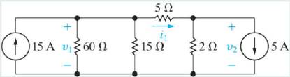
a) For the circuit shown, use the node-voltage method to find v1, v2, and i1.
b) How much power is delivered to the circuit by the 15 A source?
c) Repeat (b) for the 5 A source.
Expert Solution & Answer

Learn your wayIncludes step-by-step video

schedule06:29
Students have asked these similar questions
Question 2
A transistor is used as a switch and the waveforms are shown in Figure 2. The parameters are
Vcc = 225 V, VBE(sat) = 3 V, IB = 8 A, VCE(sat) = 2 V, Ics = 90 A, td = 0.5 µs, tr = 1 µs, ts = 3 µs, tƒ
= 2 μs, and f
10 kHz. The duty cycle is k 50%. The collector- emitter leakage current is
ICEO = 2 mA. Determine the power loss due to the collector current:
=
=
=
(a) during turn-on ton = td + tr
VCE
Vcc
(b) during conduction period tn
V CE(sat)
0
toff"
ton
Ics
0.9 Ics
(c) during turn-off toff = ts + tf
(d) during off-time tot
(e) the total average power losses PT
ICEO
0
IBS
0
Figure 2
V BE(sat)
0
主
*
td
tr
In
Is
If
to
iB
VBE
T= 1/fs
Question 1:
The beta (B) of the bipolar transistor shown in Figure 1 varies from 12 to 60. The load resistance
is Rc = 5. The dc supply voltage is VCC = 40 V and the input voltage to the base circuit is
VB = 5 V. If VCE(sat) = 1.2 V, VBE(sat) = 1.6 V, and RB = 0.8 2, calculate:
(a) the overdrive factor ODF.
(b) the forced ẞ
(c) the power loss in the transistor PT.
IB
VB
RB
+
V BE
RC
Vcc'
Ic
+
IE
Figure 1
VCE
I need help in creating a matlab code to find the currents
Chapter 4 Solutions
Electrical Circuits and Modified MasteringEngineering - With Access
Ch. 4.2 - a) For the circuit shown, use the node-voltage...Ch. 4.2 - Use the node-voltage method to find v in the...Ch. 4.3 - Use the node-voltage method to find the power...Ch. 4.4 - Use the node-voltage method to find vo in the...Ch. 4.4 - Use the node-voltage method to find v in the...Ch. 4.4 - Use the node-voltage method to find v1 in the...Ch. 4.5 - Use the mesh-current method to find (a) the power...Ch. 4.6 - Determine the number of mesh-current equations...Ch. 4.6 - Use the mesh-current method to find vo in the...Ch. 4.7 - Use the mesh-current method to find the power...
Ch. 4.7 - Use the mesh-current method to find the mesh...Ch. 4.7 - Use the mesh-current method to find the power...Ch. 4.8 - Find the power delivered by the 2 A current source...Ch. 4.8 - Find the power delivered by the 4 A current source...Ch. 4.9 - Use a series of source transformations to find the...Ch. 4.10 - Find the Thévenin equivalent circuit with respect...Ch. 4.10 - Prob. 17APCh. 4.10 - Prob. 18APCh. 4.11 - Find the Thévenin equivalent circuit with respect...Ch. 4.11 - Find the Thévenin equivalent circuit with respect...Ch. 4.12 - Find the value of R that enables the circuit shown...Ch. 4.12 - Assume that the circuit in Assessment Problem 4.21...Ch. 4 - For the circuit shown in Fig. P4.1, state the...Ch. 4 - If only the essential nodes and branches are...Ch. 4 - Assume the voltage vs in the circuit in Fig. P4.3...Ch. 4 - A current leaving a node is defined as...Ch. 4 - How many separate parts does the circuit in Fig....Ch. 4 - Use the node-voltage method to find vo in the...Ch. 4 - Find the power developed by the 40 mA current...Ch. 4 - A 50 Ω resistor is connected in series with the 40...Ch. 4 - Use the node-voltage method to find how much power...Ch. 4 - Use the node-voltage method to show that the...Ch. 4 - Use the node-voltage method to find the branch...Ch. 4 - Use the node-voltage method to find v1 and v2 in...Ch. 4 - Use the node-voltage method to find v1 and v2 in...Ch. 4 - Use the node-voltage method to find v1, v2, and v3...Ch. 4 - The circuit shown in Fig. P4.14 is a dc model of a...Ch. 4 - Use the node-voltage method to find the total...Ch. 4 - Use the node-voltage method to find vo in the...Ch. 4 - Use the node-voltage method to calculate the power...Ch. 4 - Use the node-voltage method to find the total...Ch. 4 - Use the node voltage method to find vo for the...Ch. 4 - Find the node voltages v1, v2, and v3 in the...Ch. 4 - Use the node-voltage method to find υ0 and the...Ch. 4 - Use the node-voltage method to find the value of...Ch. 4 - Use the node-voltage method to find io in the...Ch. 4 - Use the node-voltage method to find the power...Ch. 4 - Use the node-voltage method to find vo in the...Ch. 4 - Use the node-voltage method to find the branch...Ch. 4 - Use the node-voltage method to find the value of...Ch. 4 - Assume you are a project engineer and one of your...Ch. 4 - Use the node-voltage method to find the power...Ch. 4 - Show that when Eqs. 4.13, 4.14, and 4.16 are...Ch. 4 - Use the mesh-current method to find the branch...Ch. 4 - Solve Problem 4.11 using the mesh-current...Ch. 4 - Solve Problem 4.14 using the mesh-current...Ch. 4 - Solve Problem 4.26 using the mesh-current...Ch. 4 - Use the mesh-current method to find the total...Ch. 4 - Solve Problem 4.25 using the mesh-current...Ch. 4 - Solve Problem 4.17 using the mesh-current...Ch. 4 - Use the mesh-current method to find the power...Ch. 4 - Use the mesh-current method to find the power...Ch. 4 - Use the mesh-current method to find υ0 in the...Ch. 4 - Use mesh-current method to find the power...Ch. 4 -
Use the mesh-current method to solve for iΔ in...Ch. 4 - Solve Problem 4.10 using the mesh-current...Ch. 4 - Solve Problem 4.21 using the mesh-current...Ch. 4 - Use the mesh-current method to find the total...Ch. 4 - Use the mesh-current method to find how much power...Ch. 4 - Use the mesh-current method to determine which...Ch. 4 - Use the mesh-current method to find the total...Ch. 4 - Prob. 50PCh. 4 - Solve Problem 4.23 using the mesh-current...Ch. 4 - Use the mesh-current method to find the branch...Ch. 4 - Find the branch currents ia − ie for the circuit...Ch. 4 - Assume you have been asked to find the power...Ch. 4 - A 4 kΩ resistor is placed in parallel with the 10...Ch. 4 - Would you use the node-voltage or mesh- current...Ch. 4 - Prob. 57PCh. 4 - The variable de voltage source in the circuit in...Ch. 4 - Make a series of source transformations to find...Ch. 4 - Prob. 60PCh. 4 - Use source transformations to find the current io...Ch. 4 - Use a series of source transformations to find i0...Ch. 4 - Use source transformations to find vo in the...Ch. 4 - Prob. 64PCh. 4 - Find the Norton equivalent with respect to the...Ch. 4 - Prob. 66PCh. 4 - Find the Thévenin equivalent with respect to the...Ch. 4 - Prob. 68PCh. 4 - A Thévenin equivalent can also be determined from...Ch. 4 - Prob. 70PCh. 4 - Prob. 71PCh. 4 - Prob. 72PCh. 4 - The Wheatstone bridge in the circuit shown in Fig....Ch. 4 - Prob. 74PCh. 4 - Find the Norton equivalent with respect to the...Ch. 4 - Prob. 76PCh. 4 - Prob. 77PCh. 4 - Find the Thévenin equivalent with respect to the...Ch. 4 - Find the Thévenin equivalent with respect to the...Ch. 4 - Prob. 80PCh. 4 - Find the Norton equivalent with respect to the...Ch. 4 - The variable resistor in the circuit in Fig. P4.82...Ch. 4 - Prob. 83PCh. 4 - a) Calculate the power delivered for each value of...Ch. 4 - Find the value of the variable resistor Ro in the...Ch. 4 - A variable resistor R0 is connected across the...Ch. 4 - The variable resistor (R0) in the circuit in Fig....Ch. 4 - The variable resistor in the circuit in Fig. P4.91...Ch. 4 - The variable resistor (RL) in the circuit in Fig....Ch. 4 - The variable resistor (RO) in the circuit in Fig....Ch. 4 - In the circuit in Fig. P4.92, before the 5 mA...Ch. 4 - Use the principle of superposition to find the...Ch. 4 -
Use superposition to solve for and υ0 in the...Ch. 4 - Prob. 95PCh. 4 - Use the principle of superposition to find the...Ch. 4 - Prob. 97PCh. 4 - Use the principle of superposition to find the...Ch. 4 - Assume your supervisor has asked you to determine...Ch. 4 - Prob. 100PCh. 4 - Prob. 101PCh. 4 - Prob. 102PCh. 4 - Laboratory measurements or a dc voltage source...Ch. 4 - Prob. 104PCh. 4 - Prob. 105PCh. 4 - Repeat Problem 4.105 if Ig2 increases to 17 A and...Ch. 4 - Prob. 107PCh. 4 - Use the results given in Table 4.2 to predict the...
Additional Engineering Textbook Solutions
Find more solutions based on key concepts
Porter’s competitive forces model: The model is used to provide a general view about the firms, the competitors...
Management Information Systems: Managing The Digital Firm (16th Edition)
What is the purpose of the oxygen in oxygen arc cutting?
Degarmo's Materials And Processes In Manufacturing
Define the three types of recursive binary relationships, and give an example of each, other than the ones show...
Database Concepts (8th Edition)
Describe two properties that each candidate key must satisfy.
Modern Database Management
Random Number File Reader This exercise assumes you have completed Programming Exercise 7, Random Number File W...
Starting Out with Python (4th Edition)
Suppose the following bit patterns represent values stored in twos complement notation. Find the twos complemen...
Computer Science: An Overview (13th Edition) (What's New in Computer Science)
Knowledge Booster


Learn more about
Need a deep-dive on the concept behind this application? Look no further. Learn more about this topic, electrical-engineering and related others by exploring similar questions and additional content below.Similar questions
- I need help fixing this MATLAB code: as I try to get it working there were some problems:arrow_forwardI need help in construct a matlab code to find the voltage of VR1 to VR4, the currents, and the watts based on that circuit.arrow_forwardQ2: Using D flip-flops, design a synchronous counter. The counter counts in the sequence 1,3,5,7, 1,7,5,3,1,3,5,7,.... when its enable input x is equal to 1; otherwise, the counter count 0.arrow_forward
- From the collector characteristic curves and the dc load line given below, determine the following: (a) Maximum collector current for linear operation (b) Base current at the maximum collector current (c) VCE at maximum collector current. lc (mA) 600 ΜΑ 60- 500 με 50- 400 με 40- 300 μ Α 30- Q-point 200 ΜΑ 20- 10- 100 μ Α 0 VCE (V) 1 2 3 4 5 6 7 8 9 10 [6 Paarrow_forwardProcedure:- 1- Connect the cct. shown in fig.(2). a ADDS DS Fig.(2) 2-For resistive load, measure le output voltage by using oscilloscope ;then sketch this wave. 3- Measure the average values ::f VL and IL: 4- Repeat steps 2 & 3 but for RL load. Report:- 1- Calculate the D.C. output vcl age theoretically and compare it with the test value. 2- Calculate the harmonic cont :nts of the load voltage, and explain how filter components may be selected. 3- Compare between the three-phase half & full-wave uncontrolled bridge rectifier. 4- Draw the waveform for the c:t. shown in fig.(2) but after replaced Di and D3 by thyristors with a 30° and a2 = 90° 5- Draw the waveform for the cct. shown in fig.(2) but after replace the 6-diodes by 6- thyristor. 6- Discuss your results. Please solve No. 4 and 5arrow_forwardPlease I want solution by handwrittenarrow_forward
- 8 00 ! Required information Consider the circuit given below. 0/2 points awarded 3 ΚΩ www t=0 6kM Scored R 1.5i Vc 1 μF 10 V If R = 5.00 kQ, determine vao+). The value of va(0) is 1.4545 V.arrow_forwardI want to know what does it look in a breadboard circuit, because I want to created it but I not sure it is build properly, can you give me an illustuation base on this image, it do need to real, something like virutal examplearrow_forwardCharge neutrality Since doped semiconductor remains electroneutral, the concentration of negative charges equals the concentration of positive charges. n+ Na,ionized p+Nd,ionized np = n; 2 2 N-Na N N d d р + 2 2 n = Nd-Na 2 + Na - 2 Na +n₁ 2 71/2 1/2 2 2 +n Concentration of electrons and holes 1. Calculate concentrations of electrons and holes at room temperature in Si and Ge with donor concentration of 1.5x10¹7 cm³ and acceptor concentration of 8x1016 cm-3. 2. Will these concentrations change much with the temperature increase to 100°C?arrow_forward
- Answer the questions on the end of the image pleasearrow_forwardAnswer these two questions on the end of the image, please 1.Calculate intrinsic carrier concentration for Si, Ge and GaAs at temperatures -20°C, 20°C (room temperature) and 120°C 2.Compare the obtained data with n and p shown on previous slide 25arrow_forwardCan you help me achieve the requirements using Arduino? I have encountered some issues with these requirements. Q.2: Suppose you have two push buttons connected to ports (0 & 1) and four LED's connected to ports (6-9). Write a program to flash ON the odd LED's if we press the switch 0 for 4s, flash ON the even LED's if we press the switch 1 for 5s and flash ON all the LED's otherwise for 6s.arrow_forward
arrow_back_ios
SEE MORE QUESTIONS
arrow_forward_ios
Recommended textbooks for you
 Introductory Circuit Analysis (13th Edition)Electrical EngineeringISBN:9780133923605Author:Robert L. BoylestadPublisher:PEARSON
 Delmar's Standard Textbook Of ElectricityElectrical EngineeringISBN:9781337900348Author:Stephen L. HermanPublisher:Cengage Learning
 Programmable Logic ControllersElectrical EngineeringISBN:9780073373843Author:Frank D. PetruzellaPublisher:McGraw-Hill Education
 Fundamentals of Electric CircuitsElectrical EngineeringISBN:9780078028229Author:Charles K Alexander, Matthew SadikuPublisher:McGraw-Hill Education
 Electric Circuits. (11th Edition)Electrical EngineeringISBN:9780134746968Author:James W. Nilsson, Susan RiedelPublisher:PEARSON
 Engineering ElectromagneticsElectrical EngineeringISBN:9780078028151Author:Hayt, William H. (william Hart), Jr, BUCK, John A.Publisher:Mcgraw-hill Education,
Introductory Circuit Analysis (13th Edition)
Electrical Engineering
ISBN:9780133923605
Author:Robert L. Boylestad
Publisher:PEARSON
Delmar's Standard Textbook Of Electricity
Electrical Engineering
ISBN:9781337900348
Author:Stephen L. Herman
Publisher:Cengage Learning
Programmable Logic Controllers
Electrical Engineering
ISBN:9780073373843
Author:Frank D. Petruzella
Publisher:McGraw-Hill Education
Fundamentals of Electric Circuits
Electrical Engineering
ISBN:9780078028229
Author:Charles K Alexander, Matthew Sadiku
Publisher:McGraw-Hill Education
Electric Circuits. (11th Edition)
Electrical Engineering
ISBN:9780134746968
Author:James W. Nilsson, Susan Riedel
Publisher:PEARSON
Engineering Electromagnetics
Electrical Engineering
ISBN:9780078028151
Author:Hayt, William H. (william Hart), Jr, BUCK, John A.
Publisher:Mcgraw-hill Education,
Nodal Analysis for Circuits Explained; Author: Engineer4Free;https://www.youtube.com/watch?v=f-sbANgw4fo;License: Standard Youtube License