
EBK VECTOR MECHANICS FOR ENGINEERS: STA
11th Edition
ISBN: 8220102809888
Author: BEER
Publisher: YUZU
expand_more
expand_more
format_list_bulleted
Concept explainers
Videos
Textbook Question
Chapter 4.1, Problem 4.33P
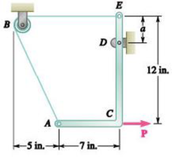
PROBLEM 4.33
A force P of magnitude 90 lb is applied to member ACDE, which is supported by a frictionless pin at D and by the cable ABE. Since the cable passes over a small pulley at B, the tension may be assumed to be the same in portions AB and BE of the cable. For the case when a = 3 in., determine (a) the tension in the cable, (b) the reaction at D.
Expert Solution & Answer
Want to see the full answer?
Check out a sample textbook solution
Students have asked these similar questions
Calculate the compression ratio of an engine with a stroke of 4.2inches a bore of 4.5 inches and a clearance volume of 6.15 cubic inches. Discuss whether or not this is a realistic compression ratio for a street engine and what octane rating of fuel it would need to run correctly
Draw the free-body diagram for the pinned assembly shown. Find the magnitude of the forces
acting on each member of the assembly.
1500 N
1500 N
C
45°
45°
45°
45°
1000 mm
An elastic bar of length L spins with angular velocity ω about an axis, as shown in the figure below. The radial acceleration at a generic point x along the bar is a(x) = ω 2 x. Due to this radial acceleration, the bar stretches along x with displacement function u(x). The displacement u(x) is governed by the following equations: ( d dx (σ(x)) + ρa(x) = 0 PDE σ(x) = E du dx Hooke’s law (1) where σ(x) is the axial stress in the rod, ρ is the mass density, and E is the (constant) Young’s modulus. The bar is pinned on the rotation axis at x = 0, and it is free at x = L.
Determine:1. Appropriate BCs for this physical problem.2. The displacement function u(x).3. The stress function σ(x).
Chapter 4 Solutions
EBK VECTOR MECHANICS FOR ENGINEERS: STA
Ch. 4.1 - Two crates, each of mass 350 kg, are placed as...Ch. 4.1 - A lever AB is hinged at C and attached to a...Ch. 4.1 - A light rod AD is supported by frictionless pegs...Ch. 4.1 - A tension of 20 N is maintained in a tape as it...Ch. 4.1 - A gardener uses a 60 N wheelbarrow to transport a...Ch. 4.1 - The gardener of Prob. 4.1 wishes to transport a...Ch. 4.1 - A 2100-lb tractor is used to lift 900 lb of grave....Ch. 4.1 - For the beam and loading shown, determine (a) the...Ch. 4.1 - A load of lumber of weight W = 25 kN is being...Ch. 4.1 - A load of lumber of weight W = 25 kN is being...
Ch. 4.1 - 4.7 A T-shaped bracket supports the four loads...Ch. 4.1 - 4.8 For the bracket and loading of Prob. 4.7,...Ch. 4.1 - Three loads are applied as shown to a light beam...Ch. 4.1 - 4.10 Three loads are applied as shown to a light...Ch. 4.1 - 4.11 For the beam of Prob. 4.10, determine the...Ch. 4.1 - For the beam of Sample Prob. 4.2, determine the...Ch. 4.1 - The maximum allowable value of each of the...Ch. 4.1 - For the beam and loading shown, determine the...Ch. 4.1 - Prob. 4.15PCh. 4.1 - Prob. 4.16PCh. 4.1 - Prob. 4.17PCh. 4.1 - Prob. 4.18PCh. 4.1 - The bracket BCD is hinged at C and attached to a...Ch. 4.1 - The ladder AB, of length L and weight W, can be...Ch. 4.1 - 4.21 The 40-ft boom AB weighs 2 kips; the distance...Ch. 4.1 - A lever AB is hinged at C and attached to a...Ch. 4.1 - 4.23 and 4.24 For each of the plates and loadings...Ch. 4.1 - 4.23 and 4.24 For each of the plates and loadings...Ch. 4.1 - A rod AB, hinged at A and attached at B to cable...Ch. 4.1 - Fig. P4.25 and P4.26 4.26 A rod AB, hinged at A...Ch. 4.1 - Prob. 4.27PCh. 4.1 - Determine the reactions at A and C when (a) = 0,...Ch. 4.1 - Prob. 4.29PCh. 4.1 - Prob. 4.30PCh. 4.1 - Neglecting friction, determine the tension in...Ch. 4.1 - Fig. P4.31 and P4.32 4.32 Neglecting friction,...Ch. 4.1 - PROBLEM 4.33 A force P of magnitude 90 lb is...Ch. 4.1 - PROBLEM 4.34 Solve Problem 4,33 for a = 6 in,...Ch. 4.1 - Bar AC supports two 400-N loads as shown. Rollers...Ch. 4.1 - PROBLEM 4.36 A light bar AD is suspended from a...Ch. 4.1 - Prob. 4.37PCh. 4.1 - Prob. 4.38PCh. 4.1 - Prob. 4.39PCh. 4.1 - 4.40 A light bar AB supports a 15-kg block at its...Ch. 4.1 - 4.41 Two slots have been cut in plate DEF, and the...Ch. 4.1 - Prob. 4.42PCh. 4.1 - The rig shown consists of a 1200-lb horizontal...Ch. 4.1 - Fig. P4.43 4.44 For the rig and crate of Prob....Ch. 4.1 - A 175-kg utility pole is used to support at C the...Ch. 4.1 - Knowing that the tension in wire BD is 1300 N,...Ch. 4.1 - Fig. P4.46 and P4.47 4.47 Determine the range of...Ch. 4.1 - Beam AD carries the two 40-lb loads shown. The...Ch. 4.1 - Fig. P4.48 and P4.49 4.49 For the beam and loading...Ch. 4.1 - Prob. 4.50PCh. 4.1 - A uniform rod AB with a length of l and weight of...Ch. 4.1 - Rod AD is acted upon by a vertical force P at end...Ch. 4.1 - A slender rod AB with a weigh of W is attached to...Ch. 4.1 - 4.54 and 4.55 A vertical load P is applied at end...Ch. 4.1 - 4.54 and 4.55 A vertical load P is applied at end...Ch. 4.1 - A collar B with a weight of W can move freely...Ch. 4.1 - A 400-lb weight is attached at A to the lever...Ch. 4.1 - Prob. 4.58PCh. 4.1 - Eight identical 500 750-mm rectangular plates,...Ch. 4.1 - Prob. 4.60PCh. 4.2 - A 500-lb cylindrical tank, 8 ft in diameter, is to...Ch. 4.2 - 4.62.Determine the reactions at A and B when a =...Ch. 4.2 - Prob. 4.63PCh. 4.2 - Prob. 4.64PCh. 4.2 - Determine the reactions at B and C when a = 30 mm.Ch. 4.2 - Prob. 4.66PCh. 4.2 - Determine the reactions at B and D when b = 60 mm....Ch. 4.2 - For the frame and loading shown, determine the...Ch. 4.2 - A 50-kg crate is attached to the trolley-beam...Ch. 4.2 - One end of rod AB rests in the corner A and the...Ch. 4.2 - For the boom and loading shown, determine (a) the...Ch. 4.2 - Prob. 4.72PCh. 4.2 - Prob. 4.73PCh. 4.2 - Prob. 4.74PCh. 4.2 - Rod AB is supported by a pin and bracket at A and...Ch. 4.2 - Solve Prob. 4.75, assuming that the 170-N force...Ch. 4.2 - Prob. 4.77PCh. 4.2 - Using the method of Sec. 4.2B, solve Prob. 4.22....Ch. 4.2 - Knowing that = 30, determine the reaction (a) at...Ch. 4.2 - Prob. 4.80PCh. 4.2 - Determine the reactions at A and B when = 50....Ch. 4.2 - Determine the reactions at A and B when = 80.Ch. 4.2 - Rod AB is bent into the shape of an arc of circle...Ch. 4.2 - A slender rod of length L is attached to collars...Ch. 4.2 - Prob. 4.85PCh. 4.2 - Prob. 4.86PCh. 4.2 - A slender rod BC with a length of L and weight W...Ch. 4.2 - A thin ring with a mass of 2 kg and radius r = 140...Ch. 4.2 - Prob. 4.89PCh. 4.2 - Prob. 4.90PCh. 4.3 - Two tape spools are attached to an axle supported...Ch. 4.3 - A 12-m pole supports a horizontal cable CD and is...Ch. 4.3 - A 20-kg cover for a roof opening is hinged at...Ch. 4.3 - END-OF-SECTION PROBLEMS 4.91 Two transmission...Ch. 4.3 - Solve Prob. 4.91, assuming that the pulley rotates...Ch. 4.3 - A small winch is used to raise a 120-lb load. Find...Ch. 4.3 - 4.94 A 4 × 8-ft sheet of plywood weighing 34 lb...Ch. 4.3 - A 250 400-mm plate of mass 12 kg and a...Ch. 4.3 - Solve Prob. 4.95 for = 60. 4.95 A 250 400-mm...Ch. 4.3 - 4.97 The 20 × 20-in. square plate shown weighs 56...Ch. 4.3 - 4.98 The 20 × 20-in. square plate shows weighs 56...Ch. 4.3 - An opening in a floor is covered by a 1 1.2-m...Ch. 4.3 - PROBLEM 4.100 Solve Problem 4.99, assuming that...Ch. 4.3 - PROBLEM 4.101 Two steel pipes AB and BC, each...Ch. 4.3 - PROBLEM 4.102 For the pipe assembly of Problem...Ch. 4.3 - PROBLEM 4.103 The 24-lb square plate shown is...Ch. 4.3 - PROBLEM 4.104 The table shown weighs 30 lb and has...Ch. 4.3 - PROBLEM 4.105 A 10-ft boom is acted upon by the...Ch. 4.3 - PROBLEM 4.106 The 6-m pole ABC is acted upon by a...Ch. 4.3 - PROBLEM 4.107 Solve Problem 4.106 for a = 1.5 m....Ch. 4.3 - Prob. 4.108PCh. 4.3 - Prob. 4.109PCh. 4.3 - Prob. 4.110PCh. 4.3 - PROBLEM 4.111 A 48-in. boom is held by a...Ch. 4.3 - PROBLEM 4.112 Solve Problem 4.111, assuming that...Ch. 4.3 - PROBLEM 4.114 The bent rod ABEF is supported by...Ch. 4.3 - Prob. 4.114PCh. 4.3 - The horizontal platform ABCD weighs 60 lb and...Ch. 4.3 - PROBLEM 4.116 The lid of a roof scuttle weighs 75...Ch. 4.3 - PROBLEM 4.117 A 100-kg uniform rectangular plate...Ch. 4.3 - Solve Prob. 4.117, assuming that cable DCE is...Ch. 4.3 - PROBLEM 4.119 Solve Prob. 4.113, assuming that the...Ch. 4.3 - PROBLEM 4.120 Solve Prob. 4.115, assuming that the...Ch. 4.3 - PROBLEM 4.121 The assembly shown is used to...Ch. 4.3 - PROBLEM 4.122 The assembly shown is welded to...Ch. 4.3 - 4.123 The rigid L-shaped member ABC is supported...Ch. 4.3 - Prob. 4.124PCh. 4.3 - The rigid L-shaped member ABF is supported by a...Ch. 4.3 - Solve Prob. 4.125, assuming that the load at C has...Ch. 4.3 - Three rods are welded together to form a corner...Ch. 4.3 - Prob. 4.128PCh. 4.3 - Frame ABCD is supported by a ball-and-socket joint...Ch. 4.3 - Prob. 4.130PCh. 4.3 - Prob. 4.131PCh. 4.3 - PROBLEM 4.132 The uniform 10kg rod AB is supported...Ch. 4.3 - The frame ACD is supported by ball-and-socket...Ch. 4.3 - Solve Prob. 4.133, assuming that cable GBH is...Ch. 4.3 - Prob. 4.135PCh. 4.3 - Prob. 4.136PCh. 4.3 - Prob. 4.137PCh. 4.3 - The pipe ACDE is supported by ball-and-socket...Ch. 4.3 - Solve Prob. 4.138, assuming that wire DF is...Ch. 4.3 - Two 2 4-ft plywood panels, each with a weight of...Ch. 4.3 - Solve Prob. 4.140, subject to the restriction that...Ch. 4 - A 3200-lb forklift truck is used to lift a 1700-lb...Ch. 4 - The lever BCD is hinged at C and attached to a...Ch. 4 - Determine the reactions at A and B when (a) h =0,...Ch. 4 - Neglecting friction and the radius of the pulley,...Ch. 4 - PROBLEM 4.146 Bar AD is attached at A and C to...Ch. 4 - PROBLEM 4.147 A slender rod AB, of weight W, is...Ch. 4 - PROBLEM 4.148 Determine the reactions at A and B...Ch. 4 - For the frame and loading shown, determine the...Ch. 4 - PROBLEM 4.150 A 200-mm lever and a 240-mm-diameter...Ch. 4 - The 45-lb square plate shown is supported by three...Ch. 4 - The rectangular plate shown weighs 75 lb and is...Ch. 4 - A force P is applied to a bent rod ABC, which may...
Knowledge Booster


Learn more about
Need a deep-dive on the concept behind this application? Look no further. Learn more about this topic, mechanical-engineering and related others by exploring similar questions and additional content below.Similar questions
- With reference to the given figure: a) Draw a free-body diagram of the structure supporting the pulley. b) Draw shear and bending moment diagrams for both the vertical and horizontal portions of the structure. 48 in. 100 lb 12 in. Cable 27 in. 12-in. pulley radius 100 lb Cablearrow_forwardConsider a standard piston engine . Draw a free body diagram of the piston. Then:a) For an A SI engine with a 100 mm bore at an instantaneous cylinder pressure of 42 bar i. Calculate the level of the combustion gas loading force on the wrist pin in kN. b) Repeat this calculationfor a forced-induction Diesel engine with a 145 mm boreat a cylinder pressure of 115 bararrow_forwardA punch press with flywheel adequate to minimize speed fluctuation produces 120 punching strokes per minute, each providing an average force of 2000 N over a stroke of 50 mm. The press is driven through a gear reducer by a shaft rotating 200 rpm. Overall efficiency is 80%. a) What power (W) is transmitted through the shaft? b) What average torque is applied to the shaft?arrow_forward
- 1.58 The crankshaft of a single-cylinder air compressor rotates 1800 rpm. The piston area is 2000 mm2 and the piston stroke is 50 mm. Assume a simple “idealized” case where the average gas pressure acting on the piston during the compression stroke is 1 MPa, and pressure during the intake stroke is negligible. The compressor is 80% efficient. A flywheel provides adequate control of the speed fluctuation. a) What motor power (kW) is required to drive the crankshaft? b) What torque is transmitted through the crankshaft?arrow_forward28. The shaft shown in Figure P5-28 is supported by bear- ings at each end, which have bores of 20.0 mm. Design the shaft to carry the given load if it is steady and the shaft is stationary. Make the dimension a as large as pos- sible while keeping the stress safe. Determine the required d 20 mm 5.4 kN d D = ? Length not to scale -α = = -125 mm 20 mm a = -250 mm- FIGURE P5-28 (Problems 28, 29, and 30)arrow_forwardThe motor shown operates at constant speed and develops a torque of 100 lb-in during normal operation. Attached to the motor shaft is a gear reducer of ratio 5:1, that is, the reducer output shaft rotates in the same direction as the motor but at one-fifth motor speed. Rotation of the reducer housing is prevented by the "torque arm" pin-connected at each end as shown. The reducer output shaft drives the load through a flexible coupling. Neglecting gravity and friction, what loads are applied to (a) the torque arm, (b) the motor output shaft, and (c) the reducer output shaft? Motor Gear reducer Flexible coupling (To load) Torque arm- Torque arm Reducer output shaft Motor Reducer Shaft rotationarrow_forward
- Please can you help with ten attatched question?arrow_forwardAn AISI 1018 steel ball with 1.100-in diameter is used as a roller between a flat plate made from 2024 T3 aluminum and a flat table surface made from ASTM No. 30 gray cast iron. Determine the maximum amount of weight that can be stacked on the aluminum plate without exceeding a maximum shear stress of 19.00 kpsi in any of the three pieces. Assume the figure given below, which is based on a typical Poisson's ratio of 0.3, is applicable to estimate the depth at which the maximum shear stress occurs for these materials. 1.0 0.8 Ratio of stress to Pmax 0.4 90 0.6 στ Tmax 0.2 0.5a a 1.5a 2a 2.5a За Distance from contact surface The maximum amount of weight that can be stacked on the aluminum plate is lbf.arrow_forwardA carbon steel ball with 27.00-mm diameter is pressed together with an aluminum ball with a 36.00-mm diameter by a force of 11.00 N. Determine the maximum shear stress and the depth at which it will occur for the aluminum ball. Assume the figure given below, which is based on a typical Poisson's ratio of 0.3, is applicable to estimate the depth at which the maximum shear stress occurs for these materials. 1.0 0.8 Ratio of stress to Pma 9 0.6 στ 24 0.4 Tmax 0.2 0 0.5a a 1.5a Z 2a 2.5a За Distance from contact surface The maximum shear stress is determined to be MPa. The depth in the aluminum ball at which the maximum shear stress will occur is determined to be [ mm.arrow_forward
- Show all work pleasearrow_forwardDraw top, side, front view With pen(cil) and paper Multi view drawing and handwriting all of itarrow_forwardA wheel of diameter 150.0 mm and width 37.00 mm carrying a load 2.200 kN rolls on a flat rail. Take the wheel material as steel and the rail material as cast iron. Assume the figure given, which is based on a Poisson's ratio of 0.3, is applicable to estimate the depth at which the maximum shear stress occurs for these materials. At this critical depth, calculate the Hertzian stresses σr, σy, σz, and Tmax for the wheel. 1.0 0.8 0, т Ratio of stress to Pmax 0.4 0.6 90 69 0.2 0.5b b 1.5b Tmax 2b Distance from contact surface The Hertizian stresses are as follows: 02 = or = -23.8 psi for the wheel =| necessary.) σy for the wheel =| MPa σz for the wheel = MPa V4 for the wheel = | MPa 2.5b ཡི 3b MPa (Include a minus sign ifarrow_forward
arrow_back_ios
SEE MORE QUESTIONS
arrow_forward_ios
Recommended textbooks for you
 Elements Of ElectromagneticsMechanical EngineeringISBN:9780190698614Author:Sadiku, Matthew N. O.Publisher:Oxford University Press
 Mechanics of Materials (10th Edition)Mechanical EngineeringISBN:9780134319650Author:Russell C. HibbelerPublisher:PEARSON
 Thermodynamics: An Engineering ApproachMechanical EngineeringISBN:9781259822674Author:Yunus A. Cengel Dr., Michael A. BolesPublisher:McGraw-Hill Education
 Control Systems EngineeringMechanical EngineeringISBN:9781118170519Author:Norman S. NisePublisher:WILEY
 Mechanics of Materials (MindTap Course List)Mechanical EngineeringISBN:9781337093347Author:Barry J. Goodno, James M. GerePublisher:Cengage Learning
 Engineering Mechanics: StaticsMechanical EngineeringISBN:9781118807330Author:James L. Meriam, L. G. Kraige, J. N. BoltonPublisher:WILEY
Elements Of Electromagnetics
Mechanical Engineering
ISBN:9780190698614
Author:Sadiku, Matthew N. O.
Publisher:Oxford University Press
Mechanics of Materials (10th Edition)
Mechanical Engineering
ISBN:9780134319650
Author:Russell C. Hibbeler
Publisher:PEARSON
Thermodynamics: An Engineering Approach
Mechanical Engineering
ISBN:9781259822674
Author:Yunus A. Cengel Dr., Michael A. Boles
Publisher:McGraw-Hill Education
Control Systems Engineering
Mechanical Engineering
ISBN:9781118170519
Author:Norman S. Nise
Publisher:WILEY
Mechanics of Materials (MindTap Course List)
Mechanical Engineering
ISBN:9781337093347
Author:Barry J. Goodno, James M. Gere
Publisher:Cengage Learning
Engineering Mechanics: Statics
Mechanical Engineering
ISBN:9781118807330
Author:James L. Meriam, L. G. Kraige, J. N. Bolton
Publisher:WILEY
EVERYTHING on Axial Loading Normal Stress in 10 MINUTES - Mechanics of Materials; Author: Less Boring Lectures;https://www.youtube.com/watch?v=jQ-fNqZWrNg;License: Standard YouTube License, CC-BY