
Concept explainers
Videos
4.23 and 4.24 For each of the plates and loadings shown, determine the reaction at A and B.
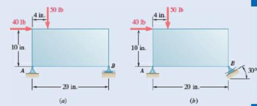
Fig. P4.23
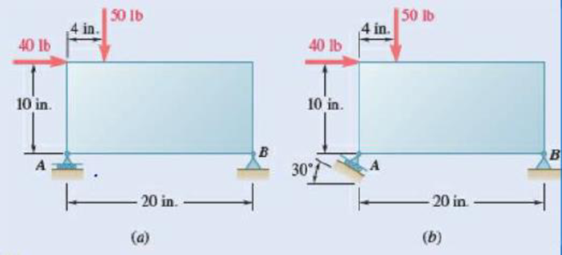
Fig. P4.24
(a)
The reaction at
Answer to Problem 4.23P
The reaction at
Explanation of Solution
Take vectors along positive
Let
The free body diagram is sketched below as figure 1.
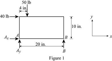
Here,
Write the expression for the moment at
Here,
Above equation implies that net moment at any point is the sum of product of each force acting on the system and perpendicular distance of the force and the point.
The moment at
Thus, the complete expression of
Here,
At equilibrium, the sum of the moment acting at
Write the expression for the net force along the
Here,
At equilibrium, the net force along the
Write the expression for the net force along the
Here,
At equilibrium, the net force along the
Let
Write the expression for the magnitude of net reaction at
Here,
Therefore, write the expression for the
Calculation:
Rearrange equation (III) to get
From figure 1, the reaction
Rearrange equation (V) to get
The negative sign indicates that the
Rearrange equation (VII) to get
Substitute
Substitute
Substitute
Therefore, the reaction at
(b)
The reaction at
Answer to Problem 4.23P
The reaction at
Explanation of Solution
Take vectors along positive
Let
The free body diagram is sketched below as figure 2.
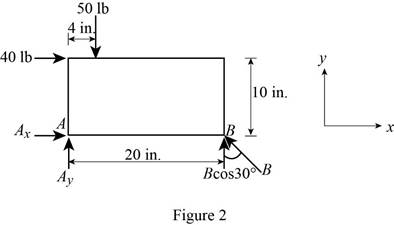
Here,
Write the expression for the moment at
Here,
Above equation implies that net moment at any point is the sum of product of each force acting on the system and perpendicular distance of the force and the point.
The moment at
Thus, the complete expression of
Here,
From figure 2 , u component of reaction
At equilibrium, the sum of the moment acting at
Write the expression for the net force along the
Here,
At equilibrium, the net force along the
Write the expression for the net force along the
Here,
At equilibrium, the net force along the
Let
Write the expression for the magnitude of net reaction at
Here,
Therefore, write the expression for the
Calculation:
Rearrange equation (III) to get
From figure 2, the reaction B is
Rearrange equation (V) to get
Substitute
Rearrange equation (VII) to get
Substitute
Substitute
Substitute
Therefore, the reaction at
Want to see more full solutions like this?
Chapter 4 Solutions
EBK VECTOR MECHANICS FOR ENGINEERS: STA


- Qu. 13 What are the indices for the Direction 2 indicated by vector in the following sketch? Qu. 14 Determine the indices for the direction A and B shown in the following cubic unit cell. please show all work step by step from material engineeringarrow_forwardThe thin-walled open cross section shown is transmitting torque 7. The angle of twist ₁ per unit length of each leg can be determined separately using the equation 01 = 3Ti GLIC 3 where G is the shear modulus, ₁ is the angle of twist per unit length, T is torque, and L is the length of the median line. In this case, i = 1, 2, 3, and T; represents the torque in leg i. Assuming that the angle of twist per unit length for each leg is the same, show that T= Lic³ and Tmaz = G01 Cmax Consider a steel section with Tallow = 12.40 kpsi. C1 2 mm L1 20 mm C2 3 mm L2 30 mm C3 2 mm L3 25 mm Determine the torque transmitted by each leg and the torque transmitted by the entire section. The torque transmitted by the first leg is | N-m. The torque transmitted by the second leg is N-m. The torque transmitted by the third leg is N-m. The torque transmitted by the entire section is N-m.arrow_forwardPlease help, make sure it's to box out and make it clear what answers go where...arrow_forward
- The cylinder floats in the water and oil to the level shown. Determine the weight of the cylinder. (rho)o=910 kg/m^3arrow_forwardPlease help, make sure it's to box out and make it clear what answers go where..arrow_forwardPlease help, make sure it's to box out and make it clear what answers go where...arrow_forward
 Elements Of ElectromagneticsMechanical EngineeringISBN:9780190698614Author:Sadiku, Matthew N. O.Publisher:Oxford University Press
 Mechanics of Materials (10th Edition)Mechanical EngineeringISBN:9780134319650Author:Russell C. HibbelerPublisher:PEARSON
 Thermodynamics: An Engineering ApproachMechanical EngineeringISBN:9781259822674Author:Yunus A. Cengel Dr., Michael A. BolesPublisher:McGraw-Hill Education
 Control Systems EngineeringMechanical EngineeringISBN:9781118170519Author:Norman S. NisePublisher:WILEY
 Mechanics of Materials (MindTap Course List)Mechanical EngineeringISBN:9781337093347Author:Barry J. Goodno, James M. GerePublisher:Cengage Learning
 Engineering Mechanics: StaticsMechanical EngineeringISBN:9781118807330Author:James L. Meriam, L. G. Kraige, J. N. BoltonPublisher:WILEY