
Videos
A light-sensing circuit is in Fig. 4.90, including a resistor that changes value under illumination (photoresistor Rlight) and a variable resistor (potentiometer Rpot). The circuit is in the Wheatstone bridge configuration such that a “balanced” condition results in Vout = 0 for a defined value of incident light and a corresponding value for Rlight. (a) Derive an algebraic expression for Vout in terms of RS, R1, R2, Rlight, and Rpot. (b) Using the numerical values given in the circuit, calculate the value of Rpot required to balance the circuit at 500 lux, where Rlight = 200 Ω. (c) If the resistance of the photoresistor decreases by 2% for a light increase to 600 lux (and assuming the resistance change with light is linear), what will the light level be if you measure Vout = 150 mV?
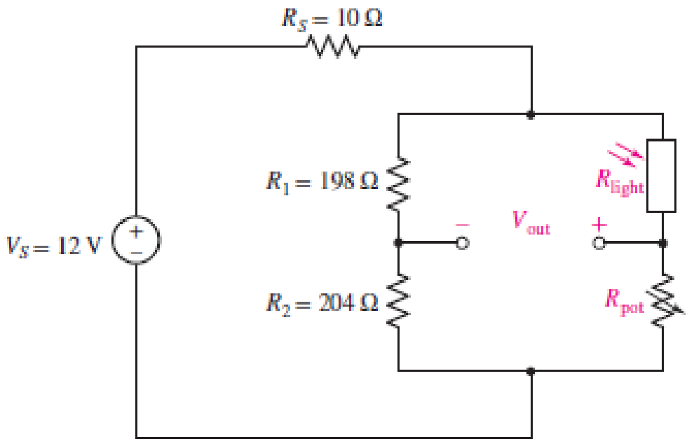
■ FIGURE 4.90
(a)
Write an algebraic expression for the output voltage
Explanation of Solution
Given data:
Refer to Figure 4.90 in the textbook.
Calculation:
The given circuit of Figure 4.90 is redrawn as shown in Figure 1.
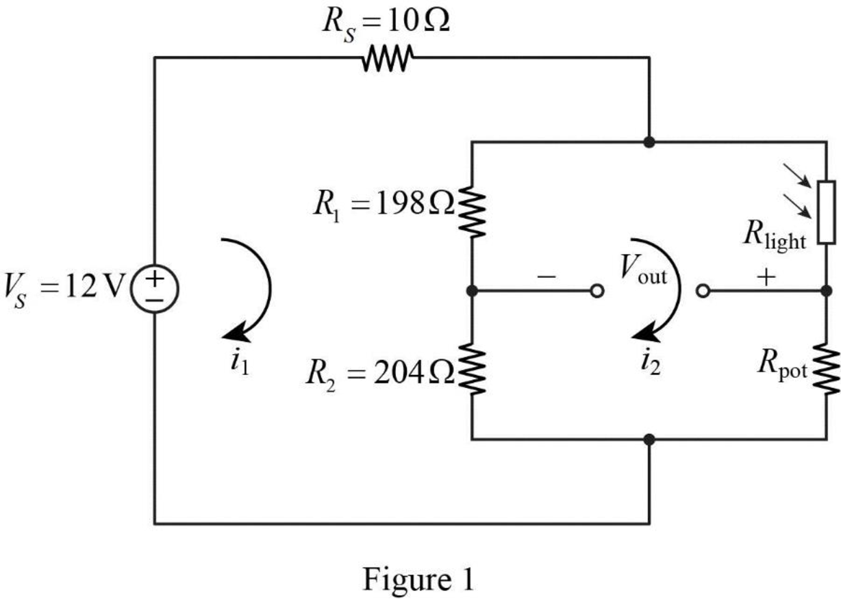
Apply Kirchhoff’s voltage law for the loop current
Apply Kirchhoff’s voltage law for the loop current
Rearrange the equation as follows,
Substitute equation (2) in equation (1).
Rearrange the equation as follows,
Substitute equation (3) in equation (2).
In Figure 1, the output voltage
Substitute equation (3) and (4) in equation (5).
Conclusion:
Thus, the output voltage
(b)
Calculate the value of variable resistor
Answer to Problem 74E
The value of variable resistor
Explanation of Solution
Given data:
Refer to Part (a).
The resistance
For balanced condition,
Calculation:
Refer to Part (a).
Substitute 0 for
Simplify the equation as follows,
Substitute
Conclusion:
Thus, the value of variable resistor
(c)
Find the light level if the resistance of the photoresistor decreases by 2% for a light increase to 600 lux with the measure of output voltage
Answer to Problem 74E
The light level is 760 lux if the resistance of the photoresistor decreases by 2% for a light increase to 600 lux with the measure of output voltage
Explanation of Solution
Given data:
Refer to Part (b).
The variable resistor
The output voltage
Calculation:
When the photoresistor resistance decreases by 2% with a light increase to 600 lux, then
Refer to Part (a), reduce the equation (6) as follows,
Substitute 12 V for
Reduce the equation as follows,
For a linear change, the light level is calculated as follows.
Conclusion:
Thus, the light level is 760 lux if the resistance of the photoresistor decreases by 2% for a light increase to 600 lux with the measure of output voltage
Want to see more full solutions like this?
Chapter 4 Solutions
Loose Leaf for Engineering Circuit Analysis Format: Loose-leaf
Additional Engineering Textbook Solutions
BASIC BIOMECHANICS
Vector Mechanics for Engineers: Statics
Modern Database Management
SURVEY OF OPERATING SYSTEMS
Starting Out With Visual Basic (8th Edition)
Electric Circuits. (11th Edition)


- 2. Determine the operation point and the small-signal model of Q₁ for each of the circuits shown in Fig. 2. Assume Is = 8 × 10-16 A, B = 100 and VA = ∞. a) 20 points b) 20 points 0.8 V RC 50 Ω + Vcc = 2.5 V 4A" Figure 2-a Rc1kQ + Vcc = 2.5 V Figure 2-barrow_forwardPlease explain in detail how to solve this question. Show detailed steps in terms of calculation and theory. thank youarrow_forwardPls show neat and whole solutionarrow_forward
- Pls show neat and whole solutionarrow_forwardPlease explain in detail how to solve this question. Include steps with calculations and theory. thank youarrow_forwardFinding crystallographic direction Z pt. 2 head pt. 1: ៩ Example 2: pt. 1 x₁ = a, y₁ = b/2, z₁ = 0 pt. 2 x2=-a, y₂ = b, Z₂ = c -a-a b-b/2 c-0 a b c tail => -2, 1/2, 1 Multiplying by 2 to eliminate the fraction -4,1,2 => [412] where the overbar represents a negative index families of directionsarrow_forward
- Crystallographic planes Crystallographic planes are denoted by Miller indices. 5b Algorithm for Miller indices 1. Read off intercepts of plane with axes in terms of a, b, c 2. Take reciprocals of intercepts 3. Reduce to smallest integer values 4. Enclose in parentheses, no commas. 353 1/3 1/5 1/3 535 (535) In the cubic system, a plane and a direction with the same indices are orthogonal. E.g. [100] direction is perpendicular to (100) plane. Correspondingly, [123] direction is perpendicular to (123) plane. [2,3,3] Plane intercepts axes at 3a, 2b, 2c 2 11 1 Reciprocal numbers are: 3'2'2 b. Indices of the plane (Miller): (2,3,3) 2 a Indices of the direction: [2,3,3] X (200) (100) (110) (111) (100) Indices of crystallographic plane can be found from cross product of indices of any two non-parallel directions in this plane.arrow_forwardCrystallographic positions Crystallographic position is denoted by three numbers, which are coefficients of the position vector, e.g. ½½½ for the red atom. Here the 'new' atom is at a/2 + b/2 + c/2 Silicon crystal has so-called "diamond type lattice". Each Si atom has 4 nearest neighbors. Diamond lattice starts with a FCC lattice and then adds four additional INTERNAL atoms at locations r = a/4+b/4+c/4 away from each of the atoms. In other words, diamond lattice is formed by two FCC lattices sifted by the vector r.arrow_forwardfind the answers for this prelabarrow_forward
- Q2: (30 Marks) Design a DC/DC converter that produce output waveforms that shown in figures below from a fixed DC source of 20 volts. Vo (Volt) 14.1 IL (Amp) 13.9 2.25 1.75 † (msec) Output voltage 0.18 0.2 t (msec) L 0.214 0.22 Output currentarrow_forward6. Build the circuit shown in Figure 2 below in PSpice. Note that the power supply V1 is a VSIN power supply in the SOURCE library. Vcc is a VDC supply found in the SOURCE library. Model this circuit using the Time Domain (Transient) Analysis Type with a Run To Time of 2 ms. A. Paste your output graph showing the voltage at the base terminal, collector terminal and at the load. B. What is the voltage gain of the circuit? (Compare the voltage amplitude at the base terminal input (across Rb2) to that at the collector terminal. C. What happens to the output voltage at the collector terminal if the value of Rb1 is reduced by a factor of 10 (to 14.7 kn)? Simulate this situation and explain the result. D. What happens to the output voltage at the collector terminal if the value of Rb1 is increased by a factor of 3 (to 441 k)? Simulate this situation and explain the result. Rb1 RC 147k 1k C2 C1 Q1 Vcc 1u VOFF = 0 Q2N3904 10Vdc VAMPL = 0.1V1 1u FREQ = 2k R_load Rb2 Re AC = 0 250 40k 20 Figure…arrow_forwardThe input reactance of 1/2 dipole with radius of 1/30 is given as shown in figure below, Assuming the wire of dipole is conductor 5.6*107 S/m, determine at f=1 GHz the a-Loss resistance, b- Radiation efficiency c-Reflection efficiency when the antenna is connected to T.L shown in the figure. Rr Ro= 50 2 1/4 RL -j100 [In(l/a) - 1.5] tan(ẞl)arrow_forward
 Introductory Circuit Analysis (13th Edition)Electrical EngineeringISBN:9780133923605Author:Robert L. BoylestadPublisher:PEARSON
 Delmar's Standard Textbook Of ElectricityElectrical EngineeringISBN:9781337900348Author:Stephen L. HermanPublisher:Cengage Learning
 Programmable Logic ControllersElectrical EngineeringISBN:9780073373843Author:Frank D. PetruzellaPublisher:McGraw-Hill Education
 Fundamentals of Electric CircuitsElectrical EngineeringISBN:9780078028229Author:Charles K Alexander, Matthew SadikuPublisher:McGraw-Hill Education
 Electric Circuits. (11th Edition)Electrical EngineeringISBN:9780134746968Author:James W. Nilsson, Susan RiedelPublisher:PEARSON
 Engineering ElectromagneticsElectrical EngineeringISBN:9780078028151Author:Hayt, William H. (william Hart), Jr, BUCK, John A.Publisher:Mcgraw-hill Education,