
Concept explainers
Videos
The LED circuit in Fig. 4.89 is used to mix colors to achieve any desired color in the RGB color palette. Use LTspice and the circuit model representing LEDs as voltage sources to see how changing the resistance R1 from 100 to 1 kΩ affects the color, with the other resistors fixed at R2 = R3 = 100 Ω. You can do this using a parameter sweep statement by defining a variable such as {rvariable} (including the curly brackets) in the value for R1. Then include a SPICE directive such as .step param rvariable 100 1k 20 to step the variable from 100 to 1000 in steps of 20. (a) Plot the current of all three LEDs as a function of R1 and explain the result. (b) Find an RGB color chart and describe how the color changes with R1, increasing from 100 to 1 kΩ. (c) Find a value of R1 that could be used to achieve a khaki color approximating RGB hex code C2BD23, RGB (194,189,35).
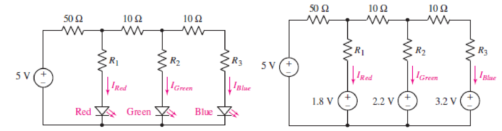
FIGURE 4.89
Want to see the full answer?
Check out a sample textbook solution
Chapter 4 Solutions
Loose Leaf for Engineering Circuit Analysis Format: Loose-leaf


- 1) A circuit is given as shown. (a) Find and label the circuit nodes. (6) Determine I, II, I₂ and V, I mm 22 +1 m 50 4 12 12v 2 ти + V ≤1652 50 mv Ми 60arrow_forwardHANDWRITTEN SOLUTION NOT USING CHATGPT PLEASEarrow_forwardDesign a full-wave rectifier power supply using a 9.52:1 transformer. Assume that the outlet is120 V rms @ 60 Hz. Further assume that the diode turn-on voltage V D(on) is 0.7 V. Pick the valueof CL such that vo has a maximum ripple of 1 V p-p . Solve for the average value of vo = Vo (notethat this may be greater than 12 V) and iD(ave) = ID.arrow_forward
- Light-emitting diodes (LEDs) are diodes made with III-V compound semiconductor materials such as aluminum gallium arsenide (AlGaAs), aluminum indium gallium phosphide (AlInGaP) or indium gallium nitride (InGaN), instead of silicon. The LEDs emit light when the device is operated under forward bias. LEDs of different colors have different turn-on voltages VD(on). For example: VD(on) : Red: ~ 1.6 V Yellow: ~ 1.7 V Green: ~ 1.8 V Blue: ~ 2.8 V White: ~ 3.8 V (a) Model these five LEDs with a simplified piecewise linear model (b) A rule of thumb is that it takes about 1 mA of current to “light” an LED while ~ 10 mA is needed for it to appear bright. Use the piecewise linear model for the LEDs, for the over-voltage indicator circuit to the right, find the values of Vin which will cause D1 or D2 to light (i.e. when ID1 or ID2 exceeds 1 mA).arrow_forwardConsider a fixed and updated instrumentation amplifier (where two resistors are lumped into one resistor), analyze the circuit if a common voltage source (VICM) is connected to two inputs. A₁ R₂ + R₁ R₂, RA www www R₁ R₁ www A3 X R₁ R₂ www www R₁₂ + Vo RA A2 V2 O- + R₂ 12 R₁arrow_forwardShow that the input impedance of a lossy transmission line of length L connected to a load impedance of Z is given by Z₁Cosh(yL) + ZoSinh(yL) Zin = Zo ZoCosh(YL) + Z₁Sihh(YL) ex Where Cosh(x) = and Sinh(x) = are the hyperbolic cosine and sine, respectively. 2 2arrow_forward
- A sinusoidal source of V = 10 and Z = 50 - j40 is connected to a 60 lossless transmission line of length 100 m with ẞ = 0.25. What is the Thevenin's equivalent of this system seen looking into the load end of the transmission line?arrow_forward2. On a distortionless transmission line, the voltage wave is given by v(L,t) = 110e0.005L Cos(10³t + 2L) +55e-0.005L Cos(108t-2L) where L is the length of the transmission line as measured from the load. If Z = 30002, find a,ẞ, vp, and Zo.arrow_forwardA 50 transmission line is to be connected to a 72 load through a 1/4 quarter wave matching transformer. (a) What must be the characteristic impedance of the transmission line that is used to form the quarter wave transformer? (b) If the frequency of operation is 7 MHz and the phase velocity through the quarter wave section is 2c/3, what is the length of the quarter wave section? You may assume the transmission line forming the quarter wave section is lossless.arrow_forward
 Introductory Circuit Analysis (13th Edition)Electrical EngineeringISBN:9780133923605Author:Robert L. BoylestadPublisher:PEARSON
 Delmar's Standard Textbook Of ElectricityElectrical EngineeringISBN:9781337900348Author:Stephen L. HermanPublisher:Cengage Learning
 Programmable Logic ControllersElectrical EngineeringISBN:9780073373843Author:Frank D. PetruzellaPublisher:McGraw-Hill Education
 Fundamentals of Electric CircuitsElectrical EngineeringISBN:9780078028229Author:Charles K Alexander, Matthew SadikuPublisher:McGraw-Hill Education
 Electric Circuits. (11th Edition)Electrical EngineeringISBN:9780134746968Author:James W. Nilsson, Susan RiedelPublisher:PEARSON
 Engineering ElectromagneticsElectrical EngineeringISBN:9780078028151Author:Hayt, William H. (william Hart), Jr, BUCK, John A.Publisher:Mcgraw-hill Education,