
Loose Leaf for Engineering Circuit Analysis Format: Loose-leaf
9th Edition
ISBN: 9781259989452
Author: Hayt
Publisher: Mcgraw Hill Publishers
expand_more
expand_more
format_list_bulleted
Concept explainers
Videos
Textbook Question
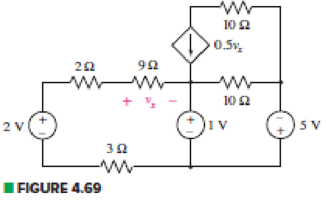
Chapter 4, Problem 42E
Define three clockwise mesh currents for the circuit of Fig. 4.69, and employ mesh analysis to obtain a value for each.
Expert Solution & Answer
Want to see the full answer?
Check out a sample textbook solution
Students have asked these similar questions
A
circuit is given as shown.
(a) Find and label the circuit nodes.
(6) Determine I, I₁, I2 and V₂
I₂
+1
I
12V
ww
22
2
ти
+
보통 162
-
ти
4
52
12
50
602
I
1
Mw
a) A silicon wafer is uniformly doped p-type with NA=10¹³/cm³. At T=0K, what are the equilibrium
hole and electron concentrations?
1016
1015
Ge
101
Si
1013
1012
GaAs
10"
(( uວ) uot¤ງແລ້ວuo ວາ.ຂ ວາsuuuT
0101
601
801
107
10%
Determine the equilibrium electron and hole concentrations inside a uniformly doped sample of Si
under the following conditions. (n; =1010/cm³ at 300K)
a) T 300 K, NA << ND, ND = 1015/cm³
b) T 300 K, NA = 9X10¹⁵/cm³, ND = 1016/cm³
c) T = 450 K, NA = 0, ND = 1014/cm³
d) T = 650 K, NA = 0, ND = 1014/cm³
10°
200
300
400
500
600
700
T(K)
Chapter 4 Solutions
Loose Leaf for Engineering Circuit Analysis Format: Loose-leaf
Ch. 4.1 - For the circuit of Fig. 4.3, determine the nodal...Ch. 4.1 - For the circuit of Fig. 4.5, compute the voltage...Ch. 4.1 - For the circuit of Fig. 4.8, determine the nodal...Ch. 4.2 - For the circuit of Fig. 4.11, compute the voltage...Ch. 4.3 - Determine i1 and i2 in the circuit in Fig. 4.19....Ch. 4.3 - Determine i1 and i2 in the circuit of Fig 4.21....Ch. 4.3 - Determine i1 in the circuit of Fig. 4.24 if the...Ch. 4.4 - Determine the current i1 in the circuit of Fig....Ch. 4.4 - Determine v3 in the circuit of Fig. 4.28. FIGURE...Ch. 4 - Solve the following systems of equations: (a) 2v2 ...
Ch. 4 - (a) Solve the following system of equations:...Ch. 4 - (a) Solve the following system of equations:...Ch. 4 - Correct (and verify by running) the following...Ch. 4 - In the circuit of Fig. 4.35, determine the current...Ch. 4 - Calculate the power dissipated in the 1 resistor...Ch. 4 - For the circuit in Fig. 4.37, determine the value...Ch. 4 - With the assistance of nodal analysis, determine...Ch. 4 - Prob. 9ECh. 4 - For the circuit of Fig. 4.40, determine the value...Ch. 4 - Use nodal analysis to find vP in the circuit shown...Ch. 4 - Prob. 12ECh. 4 - Prob. 13ECh. 4 - Determine a numerical value for each nodal voltage...Ch. 4 - Prob. 15ECh. 4 - Using nodal analysis as appropriate, determine the...Ch. 4 - Prob. 17ECh. 4 - Determine the nodal voltages as labeled in Fig....Ch. 4 - Prob. 19ECh. 4 - Prob. 20ECh. 4 - Employing supernode/nodal analysis techniques as...Ch. 4 - Prob. 22ECh. 4 - Prob. 23ECh. 4 - Prob. 24ECh. 4 - Repeat Exercise 23 for the case where the 12 V...Ch. 4 - Prob. 26ECh. 4 - Prob. 27ECh. 4 - Determine the value of k that will result in vx...Ch. 4 - Prob. 29ECh. 4 - Prob. 30ECh. 4 - Prob. 31ECh. 4 - Determine the currents flowing out of the positive...Ch. 4 - Obtain numerical values for the two mesh currents...Ch. 4 - Use mesh analysis as appropriate to determine the...Ch. 4 - Prob. 35ECh. 4 - Prob. 36ECh. 4 - Find the unknown voltage vx in the circuit in Fig....Ch. 4 - Prob. 38ECh. 4 - Prob. 39ECh. 4 - Determine the power dissipated in the 4 resistor...Ch. 4 - (a) Employ mesh analysis to determine the power...Ch. 4 - Define three clockwise mesh currents for the...Ch. 4 - Prob. 43ECh. 4 - Prob. 44ECh. 4 - Prob. 45ECh. 4 - Prob. 46ECh. 4 - Prob. 47ECh. 4 - Prob. 48ECh. 4 - Prob. 49ECh. 4 - Prob. 50ECh. 4 - Prob. 51ECh. 4 - Prob. 52ECh. 4 - For the circuit represented schematically in Fig....Ch. 4 - The circuit of Fig. 4.80 is modified such that the...Ch. 4 - The circuit of Fig. 4.81 contains three sources....Ch. 4 - Solve for the voltage vx as labeled in the circuit...Ch. 4 - Consider the five-source circuit of Fig. 4.83....Ch. 4 - Replace the dependent voltage source in the...Ch. 4 - After studying the circuit of Fig. 4.84, determine...Ch. 4 - Prob. 60ECh. 4 - Employ LTspice (or similar CAD tool) to verify the...Ch. 4 - Employ LTspice (or similar CAD tool) to verify the...Ch. 4 - Employ LTspice (or similar CAD tool) to verify the...Ch. 4 - Verify numerical values for each nodal voltage in...Ch. 4 - Prob. 65ECh. 4 - Prob. 66ECh. 4 - Prob. 67ECh. 4 - Prob. 68ECh. 4 - Prob. 69ECh. 4 - (a) Under what circumstances does the presence of...Ch. 4 - Referring to Fig. 4.88, (a) determine whether...Ch. 4 - Consider the LED circuit containing a red, green,...Ch. 4 - The LED circuit in Fig. 4.89 is used to mix colors...Ch. 4 - A light-sensing circuit is in Fig. 4.90, including...Ch. 4 - Use SPICE to analyze the circuit in Exercise 74 by...
Knowledge Booster


Learn more about
Need a deep-dive on the concept behind this application? Look no further. Learn more about this topic, electrical-engineering and related others by exploring similar questions and additional content below.Similar questions
- b) A semiconductor is doped with an impurity concentration N such that N >> n; and all the impurities are ionized. Also, n = N and p = n2/N. Is the impurity a donor or an acceptor? Explain.arrow_forwardd) For a silicon sample maintained at T=300K, the Fermi level is located 0.259 eV above the intrinsic Fermi level. What are the hole and electron concentrations?arrow_forwarde) In a nondegenerate germanium sample maintained under equilibrium conditions near room temperature, it is known that n=10¹³/cm³, n = 2p, and NA 0. Determine n and ND.arrow_forward
- Solve fo the voltage across the 1kohm resistor using superposition for the three following cases: only V1 present, only V2 present, and both V1 and V2 present.arrow_forwardSemiconductor A has a band gap of 1eV, while semiconductor B has a band gap of 2eV. What is the ration of the intrinsic carrier concentrations in the two materials (n₁A/NB) at 300 K. Assume any differences in the carrier effective masses may be neglected.arrow_forwardc) The electron concentration in a piece of Si maintained at 300K under equilibrium conditions is 105/cm³. What is the hole concentration?arrow_forward
- 5. Represent the following system in state-space form. Write A, B, C and D clearly in your answer. d³y d²y dt3 - +5y=2u dt²arrow_forward3. Find the transfer function H(s) and frequency response H (w) of the following system whose differential equation is given by d¹y d³y +3. dy +5 dt4 dt3 dt - d²u du 4y = - 5 dt² dtarrow_forward1. Consider a plant that you want to control. The input u(t) and output y(t) of the plant are related by y(t) = 7 u(t) + w(t) where w(t) is an additive disturbance at the output which is bounded by -0.5 w(t) ≤0.5 for all time t. You want to build a controller so that the output follows a constant reference signal r(t) = where -15 ≤≤ 15. You will consider both open-loop and closed-loop for this problem. a) Sketch the block diagram of the plant. b) Please build an open-loop controller that sets the output to 7, assuming the disturbance is ignored. Please show your controller both as an equation and a block diagram. c) Say that you use the open-loop controller in part b, but now the disturbance w(t) is present. What is the maximum possible magnitude of error in the output for the reference signal? Suppose you have designed a feedback control for the plant where the controller has the form u(t) = K(r(t) − y(t)). Here K is the gain constant of the controller that you will design. d) Please…arrow_forward
- 2. Suppose the Laplace transform of a causal signal x(t) is given by s² +2 X(s) = S³ + 1 Using the lookup tables for standard Laplace transforms and the Laplace transform properties, find the Laplace transforms of the following signals. You do not need to simplify the expressions. a) x₁(t) = e² x(t) + 38(t − 1) − (t − 2)² u(t − 2) b) x2(t) = x(2t - 1) + et u(t − 2)arrow_forwardPlease explain in detail the steps to solve this. Thank youarrow_forward6. Answer the following questions. Take help from ChatGPT to answer these questions (if you need). But write the answers briefly using your own words with no more than two sentences and make sure you check whether ChatGPT is giving you the appropriate answers in our context. a) What is the difference between a regulator and a servo system? Which is harder to build? b) What are the advantages and drawbacks of manual control systems over automatic ones? c) Does transfer exist for the non-linear systems? d) Explain the convolution property of the Laplace transform. e) What are the advantages of using state-space representation?arrow_forward
arrow_back_ios
SEE MORE QUESTIONS
arrow_forward_ios
Recommended textbooks for you
 Introductory Circuit Analysis (13th Edition)Electrical EngineeringISBN:9780133923605Author:Robert L. BoylestadPublisher:PEARSON
 Delmar's Standard Textbook Of ElectricityElectrical EngineeringISBN:9781337900348Author:Stephen L. HermanPublisher:Cengage Learning
 Programmable Logic ControllersElectrical EngineeringISBN:9780073373843Author:Frank D. PetruzellaPublisher:McGraw-Hill Education
 Fundamentals of Electric CircuitsElectrical EngineeringISBN:9780078028229Author:Charles K Alexander, Matthew SadikuPublisher:McGraw-Hill Education
 Electric Circuits. (11th Edition)Electrical EngineeringISBN:9780134746968Author:James W. Nilsson, Susan RiedelPublisher:PEARSON
 Engineering ElectromagneticsElectrical EngineeringISBN:9780078028151Author:Hayt, William H. (william Hart), Jr, BUCK, John A.Publisher:Mcgraw-hill Education,
Introductory Circuit Analysis (13th Edition)
Electrical Engineering
ISBN:9780133923605
Author:Robert L. Boylestad
Publisher:PEARSON
Delmar's Standard Textbook Of Electricity
Electrical Engineering
ISBN:9781337900348
Author:Stephen L. Herman
Publisher:Cengage Learning
Programmable Logic Controllers
Electrical Engineering
ISBN:9780073373843
Author:Frank D. Petruzella
Publisher:McGraw-Hill Education
Fundamentals of Electric Circuits
Electrical Engineering
ISBN:9780078028229
Author:Charles K Alexander, Matthew Sadiku
Publisher:McGraw-Hill Education
Electric Circuits. (11th Edition)
Electrical Engineering
ISBN:9780134746968
Author:James W. Nilsson, Susan Riedel
Publisher:PEARSON
Engineering Electromagnetics
Electrical Engineering
ISBN:9780078028151
Author:Hayt, William H. (william Hart), Jr, BUCK, John A.
Publisher:Mcgraw-hill Education,
Nodal Analysis for Circuits Explained; Author: Engineer4Free;https://www.youtube.com/watch?v=f-sbANgw4fo;License: Standard Youtube License