
Videos
(a) Employ mesh analysis to determine the power dissipated by the 1 Ω resistor in the circuit represented schematically by Fig. 4.68. (b) Check your answer using nodal analysis.
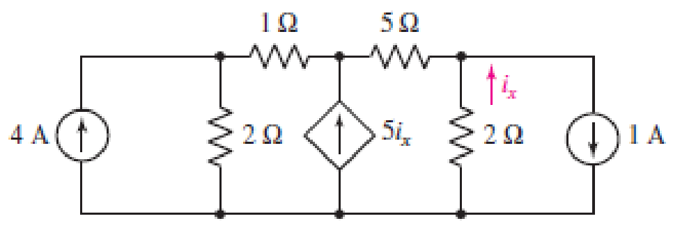
■ FIGURE 4.68
(a)
Employ mess analysis to find the power dissipated by the
Answer to Problem 41E
The power dissipated by the
Explanation of Solution
Calculation:
The circuit diagram is redrawn as shown in Figure 1,
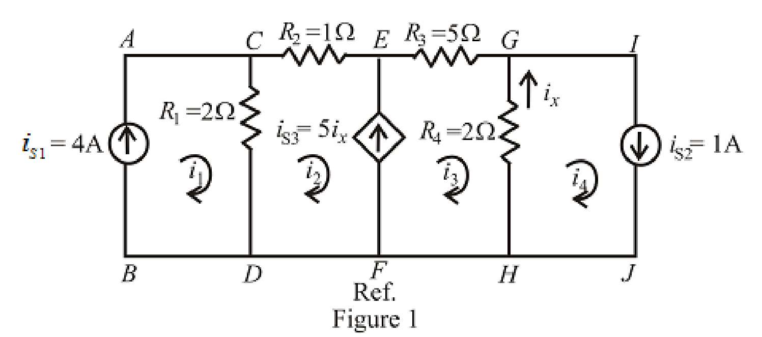
Refer to the redrawn Figure 1,
Apply KVL in the mesh
Here,
The expression for the current flowing in the branch
Here,
The expression for the current flowing in the branch
Here,
The expression for the power dissipated by the
Here,
Refer to the redrawn Figure 1,
Substitute
Rearrange equation (5),
Substitute
Substitute
Substitute
Rearrange the above equation for
Substitute
Rearrange for
Substitute
Substitute
Conclusion:
Thus, the power dissipated by the
(b)
Check the answer by nodal analysis.
Explanation of Solution
Formula used:
Refer to the redrawn Figure 1,
Apply KCL at node
Here,
Apply KCL at node
Here,
The expression for the current flowing in the branch
Apply KCL at node
Here,
The expression for the power dissipated by the
Here,
Calculation:
Refer to the redrawn Figure 1,
Substitute
Substitute
Substitute
Substitute
Substitute
Rearrange equation (13), (14) and (15),
The equations so formed can be written in matrix form as,
Therefore, by Cramer’s rule,
The determinant of the coefficient matrix is as follows,
The 1st determinant is as follows,
The 2nd determinant is as follows,
The 3rd determinant is as follows,
Simplify for
Simplify for
Simplify for
Substitute
So, the power dissipated by the
Conclusion:
Thus, the answer is checked by using nodal analysis.
Want to see more full solutions like this?
Chapter 4 Solutions
Loose Leaf for Engineering Circuit Analysis Format: Loose-leaf


- I need help with this problem and an explanation of the solution for the image described below. (Introduction to Signals and Systems)arrow_forwardNO AI PLEASE.arrow_forward2-3) For each of the two periodic signals in the figures below, find the exponential Fourier series and sketch the magnitude and angle spectra. -5 ΟΙ 1 1- (a) (b) -20π -10x -π Π 10m 20m 1-arrow_forward
- I need help with this problem and an explanation of the solution for the image described below. (Introduction to Signals and Systems)arrow_forwardIn the op-amp circuit shown in Fig. P8.32,uin(t) = 12cos(1000t) V,R = 10 k Ohm , RL = 5 k Ohm, and C = 1 μF. Determine the complexpower for each of the passive elements in the circuit. Isconservation of energy satisfied?arrow_forward2-4) Similar to Lathi & Ding prob. 2.9-4 (a) For signal g(t)=t, find the exponential Fourier series to represent g(t) over the interval(0, 1). (b) Sketch the original signal g(t) and the everlasting signal g'(t) represented by the same Fourier series. (c) Verify Parseval's theorem [eq. (2.103b)] for g'(t), given that: = n 1 6arrow_forward
 Introductory Circuit Analysis (13th Edition)Electrical EngineeringISBN:9780133923605Author:Robert L. BoylestadPublisher:PEARSON
 Delmar's Standard Textbook Of ElectricityElectrical EngineeringISBN:9781337900348Author:Stephen L. HermanPublisher:Cengage Learning
 Programmable Logic ControllersElectrical EngineeringISBN:9780073373843Author:Frank D. PetruzellaPublisher:McGraw-Hill Education
 Fundamentals of Electric CircuitsElectrical EngineeringISBN:9780078028229Author:Charles K Alexander, Matthew SadikuPublisher:McGraw-Hill Education
 Electric Circuits. (11th Edition)Electrical EngineeringISBN:9780134746968Author:James W. Nilsson, Susan RiedelPublisher:PEARSON
 Engineering ElectromagneticsElectrical EngineeringISBN:9780078028151Author:Hayt, William H. (william Hart), Jr, BUCK, John A.Publisher:Mcgraw-hill Education,