
Electrical Wiring Residential
18th Edition
ISBN: 9781285170954
Author: Ray C. Mullin, Phil Simmons
Publisher: Cengage Learning
expand_more
expand_more
format_list_bulleted
Videos
Textbook Question
thumb_up100%
Chapter 4, Problem 49R
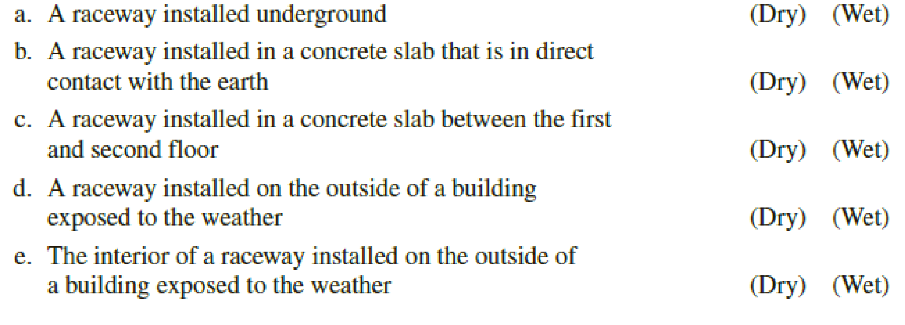
Circle the correct answer defining the type of location:
Expert Solution & Answer

Trending nowThis is a popular solution!

Students have asked these similar questions
HANDWRITTEN SOLUTION NOT USING CHATGPT PLEASE
Design a full-wave rectifier power supply using a 9.52:1 transformer. Assume that the outlet is120 V rms @ 60 Hz. Further assume that the diode turn-on voltage V D(on) is 0.7 V. Pick the valueof CL such that vo has a maximum ripple of 1 V p-p . Solve for the average value of vo = Vo (notethat this may be greater than 12 V) and iD(ave) = ID.
Light-emitting diodes (LEDs) are diodes made with III-V compound semiconductor materials such as aluminum gallium arsenide (AlGaAs), aluminum indium gallium phosphide (AlInGaP) or indium gallium nitride (InGaN), instead of silicon. The LEDs emit light when the device is operated under forward bias. LEDs of different colors have different turn-on voltages VD(on). For example:
VD(on) :
Red: ~ 1.6 V
Yellow: ~ 1.7 V
Green: ~ 1.8 V
Blue: ~ 2.8 V
White: ~ 3.8 V
(a) Model these five LEDs with a simplified piecewise linear model
(b) A rule of thumb is that it takes about 1 mA of current to “light” an LED while ~ 10 mA is needed for it to appear bright. Use the piecewise linear model for the LEDs, for the over-voltage indicator circuit to the right, find the values of Vin which will cause D1 or D2 to light (i.e. when ID1 or ID2 exceeds 1 mA).
Chapter 4 Solutions
Electrical Wiring Residential
Ch. 4 - The largest size solid conductor generally...Ch. 4 - What is the minimum branch-circuit wire size that...Ch. 4 - What exceptions, if any, are there to the answer...Ch. 4 - What determines the ampacity of a wire?Ch. 4 - What unit of measurement is used for the diameter...Ch. 4 - What unit of measurement is used for the...Ch. 4 - What is the voltage rating of the conductors in...Ch. 4 - Indicate the allowable ampacity of the following...Ch. 4 - Prob. 9RCh. 4 - What are the colors of the conductors in...
Ch. 4 - For nonmetallic-sheathed cable, may the...Ch. 4 - Prob. 12RCh. 4 - Under what condition may nonmetallic-sheathed...Ch. 4 - a. What is the maximum distance permitted between...Ch. 4 - Prob. 15RCh. 4 - Prob. 16RCh. 4 - Prob. 17RCh. 4 - Prob. 18RCh. 4 - Prob. 19RCh. 4 - Circle the correct answer to the following...Ch. 4 - When running Type NM cable through a bored hole in...Ch. 4 - Where is the main service-entrance panel located...Ch. 4 - Is it permitted to use flexible metal conduit over...Ch. 4 - Liquidtight flexible metal conduit may serve as a...Ch. 4 - It is permissible for an electrician to connect...Ch. 4 - Terminals of switches and receptacles marked...Ch. 4 - Wire connectors marked AL/CU are suitable for use...Ch. 4 - A wire connector bearing no marking or reference...Ch. 4 - When Type NM cable is run through a floor, it must...Ch. 4 - When nonmetallic-sheathed cables are bunched or...Ch. 4 - In diagrams A and B, nonmetallic-sheathed cable is...Ch. 4 - The marking on the outer jacket of a...Ch. 4 - A 120-volt branch circuit supplies a resistive...Ch. 4 - In problem 35, it is desired to keep the voltage...Ch. 4 - Prob. 37RCh. 4 - The allowable ampacity of a 4 AWG THHN from Table...Ch. 4 - If, because of some obstruction in a wall space,...Ch. 4 - The recessed fluorescent luminaires installed in...Ch. 4 - Prob. 41RCh. 4 - What size overcurrent device protects the...Ch. 4 - May the 20-ampere small-appliance branch circuits...Ch. 4 - A 30-ampere branch circuit is installed for an...Ch. 4 - In many areas, metal framing members are being...Ch. 4 - Are set screwtype connectors permitted to be used...Ch. 4 - Most armored cable today has 90C conductors. What...Ch. 4 - If you saw two different types of SE cables, how...Ch. 4 - Circle the correct answer defining the type of...
Additional Engineering Textbook Solutions
Find more solutions based on key concepts
How are relationships between tables expressed in a relational database?
Modern Database Management
A nozzle at A discharges water with an initial velocity of 36 ft/s at an angle with the horizontal. Determine ...
Vector Mechanics For Engineers
CONCEPT QUESTIONS
15.CQ3 The ball rolls without slipping on the fixed surface as shown. What is the direction ...
Vector Mechanics for Engineers: Statics and Dynamics
How is the hydrodynamic entry length defined for flow in a pipe? Is the entry length longer in laminar or turbu...
Fluid Mechanics: Fundamentals and Applications
1.2 Explain the difference between geodetic and plane
surveys,
Elementary Surveying: An Introduction To Geomatics (15th Edition)
What is an uninitialized variable?
Starting Out with Programming Logic and Design (5th Edition) (What's New in Computer Science)
Knowledge Booster


Learn more about
Need a deep-dive on the concept behind this application? Look no further. Learn more about this topic, electrical-engineering and related others by exploring similar questions and additional content below.Similar questions
- Consider a fixed and updated instrumentation amplifier (where two resistors are lumped into one resistor), analyze the circuit if a common voltage source (VICM) is connected to two inputs. A₁ R₂ + R₁ R₂, RA www www R₁ R₁ www A3 X R₁ R₂ www www R₁₂ + Vo RA A2 V2 O- + R₂ 12 R₁arrow_forwardShow that the input impedance of a lossy transmission line of length L connected to a load impedance of Z is given by Z₁Cosh(yL) + ZoSinh(yL) Zin = Zo ZoCosh(YL) + Z₁Sihh(YL) ex Where Cosh(x) = and Sinh(x) = are the hyperbolic cosine and sine, respectively. 2 2arrow_forwardA sinusoidal source of V = 10 and Z = 50 - j40 is connected to a 60 lossless transmission line of length 100 m with ẞ = 0.25. What is the Thevenin's equivalent of this system seen looking into the load end of the transmission line?arrow_forward
- 2. On a distortionless transmission line, the voltage wave is given by v(L,t) = 110e0.005L Cos(10³t + 2L) +55e-0.005L Cos(108t-2L) where L is the length of the transmission line as measured from the load. If Z = 30002, find a,ẞ, vp, and Zo.arrow_forwardA 50 transmission line is to be connected to a 72 load through a 1/4 quarter wave matching transformer. (a) What must be the characteristic impedance of the transmission line that is used to form the quarter wave transformer? (b) If the frequency of operation is 7 MHz and the phase velocity through the quarter wave section is 2c/3, what is the length of the quarter wave section? You may assume the transmission line forming the quarter wave section is lossless.arrow_forwardWhat is the SWR on a transmission line if the forward power arriving at the load is 5W but only 4.6W is dissipated by the load?arrow_forward
- Please do not send the AI solution as it is full of errors. Solve the question yourself, please. Q- If you have a unipolar winding stepper motor, draw the driver and the control circuit. In subject (A stepper motor driver circuit and direction control using Arduino microcontroller)arrow_forward1- Draw the complete circuit diagram that illustrates the experiment concept as in figure 5 by showing the pins number. Show the following in your plot (Arduino board, steppermotor coils and the driver circuit). Note: The drawing should be on paper and not with artificial intelligence, please.arrow_forwardIn the circuit shown, find the following: 1) The current Ix. 2) The average power dissipated in the capacitor. 3) The total average power dissipated in the two resistors. 4) The average power of the independent voltage source and specify whether it is supplied or absorbed. 5) The total impedance seen from the terminals of the independent voltage source (Z=V/I). 20 -201 12/00V(+ 21 www 202arrow_forward
- 2- If you have a unipolar winding stepper motor, draw the driver and the control circuit. Note: The drawing is on paper.arrow_forwardGiven the following reaction system, where Xo is the input, i.e u(t) = k₁ × Xo: $Xo -> x1; k1*Xo x2; k2*x1 x1 2 x2 ->%; k3*x2^2 x2 ->; k4*x2 Xo 1; k1 = 0.4 k2 4.5; k3 = 0.75 k4= 0.2 a) Build the model in Tellurium and run a simulation. Compute the Jacobian at steady state using the method getFull Jacobian(). Make sure you are at steady state! b) Write out the values for n and p c) Write out the differential equations. d) Write out the state space representation in terms of the rate constants etc. e) Compute the values in the Jacobian matrix from d) by substituting the values of the rate constants etc and any data you need from the simulation. f) Confirm that the Jacobian you get in e) is the same as the one computed from the simulation in a). g) Is the system stable or not? If you find an eigenvalue of zero, that means the system is marginally stable. You can get the eigenvalues using the tellurium method r.getFullEigenvalues()arrow_forwardSolve by Pen and Paper not using chatgpt or AIarrow_forward
arrow_back_ios
SEE MORE QUESTIONS
arrow_forward_ios
Recommended textbooks for you
 EBK ELECTRICAL WIRING RESIDENTIALElectrical EngineeringISBN:9781337516549Author:SimmonsPublisher:CENGAGE LEARNING - CONSIGNMENT
EBK ELECTRICAL WIRING RESIDENTIAL
Electrical Engineering
ISBN:9781337516549
Author:Simmons
Publisher:CENGAGE LEARNING - CONSIGNMENT
Types of Systems; Author: Neso Academy;https://www.youtube.com/watch?v=IRdDcSO_fQw;License: Standard youtube license