
(a)
To select:
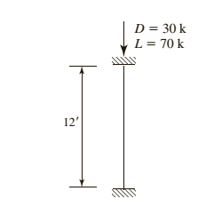
American standard channel for the given compression member using LRFD.
Answer to Problem 4.8.4P
Explanation of Solution
Given information:
Given compression member is :

Calculation:
Calculate the factored load by LRFD by using the equation.
Here
Substitute
Try a C section
AISC must be used, as this shape is non slender and is neither a double angle nor a tee shape
Check the effective slenderness ratio about y-axis using the formula.
Here K is the effective length factor
L is the length of the member between the supports.
r is the radius of gyration
Take the properties steel from the AISC steel table. K value depends on the end conditions
Calculate the elastic buckling stress using the formula.
Check for slenderness ratio by using the formula.
Here
Substitute
Since
Calculate the nominal compressive strength of column using the formula.
Substitute,
=
=
Calculate design strength of the column using by LRFD method
Here we have
Check the effective slenderness ratio about x-axis using the formula.
Substitute
From the manual companion CD:
Calculate the elastic buckling stress using the formula.
Calculate the value of
Calculate the total stress by equation
Calculate the value of
In order to determine which compressive strength equation to be use, compare the value of
Since
Calculate the maximum strength by using the formula.
.
Conclusion:
(b)
To select:
American standard channel for the given compression member using ASD.
Answer to Problem 4.8.4P
Explanation of Solution
Given information:
Given compression member is
Calculation:
Calculate the factored load by LRFD by using the equation.
He re
Substitute
Try a C section
AISC must be used, as this shape is non slender and is neither a double angle nor a tee shape
Check the effective slenderness ratio about y-axis using the formula
Here K is the effective length factor
L is the length of the member between the supports
r is the radius of gyration
Take the properties steel from the AISC steel table. K value depends on the end conditions
Calculate the elastic buckling stress using the formula.
Check for slenderness ratio by using the formula.
Here
Substitute
Since
Calculate the nominal compressive strength of column using the formula.
Substitute,
=
=
Calculate design strength of the column using by ASD method.
Here we have
Check the effective slenderness ratio about x-axis using the formula.
Substitute
From the manual companion CD:
Calculate the elastic buckling stress using the formula.
Calculate the value of
Calculate the total stress by equation
Calculate the value of
In order to determine which compressive strength equation to be use, compare the value of
Since
Calculate the maximum strength by using the formula.
Conclusion:
Want to see more full solutions like this?
Chapter 4 Solutions
Steel Design (Activate Learning with these NEW titles from Engineering!)

- 8.2 onlyarrow_forward5.6 A section of highway has the following flow- density relationship q = 50k - 0.156k2 [with q in veh/h and k in veh/mi]. What is the capacity of the highway section, the speed at capacity, and the density when the highway is at one-quarter of its capacity?arrow_forward8.20 Two routes connect a suburban area and a city, with route travel times (in minutes) given by the expressions t₁ = 6 + 8(x₁/c₁) and t₂ = 10 + 3(x2/c2), where the x's are expressed in thousands of vehicles per hour and the c's are the route capacities in thousands of vehicles per hour. Initially, the capacities of routes 1 and 2 are 4000 and 2000 veh/h, respectively. A reconstruction project on route 1 reduces the capacity to 3000 veh/h, but total traffic demand is unaffected. Observational studies note a 35.28-second increase in average travel time on route 1 and a 68.5% increase in flow on route 2 after reconstruction begins. User-equilibrium conditions exist before and during reconstruction. If both routes are always used, determine equilibrium flows and travel times before and after reconstruction begins.arrow_forward
- 8.19 Three routes connect an origin and a destination with performance functions t₁ = 8+ 0.5x1, t2 = 1 + 2x2, and t3 = 3 + 0.75x3, with the x's expressed in thousands of vehicles per hour and the 's expressed in minutes. If the peak-hour traffic demand is 3400 vehicles, determine user-equilibrium traffic flows.arrow_forward8.8 onlyarrow_forward8.4 Consider a Poisson regression model for the number of social/recreational trips generated during a peak-hour period that is estimated by (see Eq. 8.3) BZ = -0.75 +0.025(household size) + 0.008(annual household income, in thousands of dollars) + 0.10(number of nonworking household members). Suppose a household has five members (three of whom work) and an annual income of $100,000. What is the expected number of peak-hour social/recreational trips, and what is the probability that the household will not make a peak-hour social/recreational trip?arrow_forward
- 8.15 An origin-destination pair is connected by a route with a performance function t₁ = 8+ x1, and another with a function t₂ = 1 + 2x2 (with x's in thousands of vehicles per hour and t's in minutes). If the total origin-destination flow is 4000 veh/h, determine user-equilibrium and system-optimal route travel times, total travel time (in vehicle minutes), and route flows.arrow_forward8.13 Consider the situation described in Problem 8.11. If the total number of trips remains constant, determine the amount of amusement floor space that must be added to destination 2 to attract an additional 50 social/recreational trips.arrow_forward5- A basic freeway has 3 lanes in each direction and is on flat terrain. It has a jam density of 190 veh/km and a capacity of 4750 veh/h. The spot speed of 5 cars was collected at the midpoint of a 3.4 km segment of this freeway. Vehicle Speed (km/hr) 1 86 2 89 3 95 4 5 99 100 a) Calculate the space mean speed b) Calculate the free flow speed based on the given information c) A directional weekday peak-hour volume of 4640 vehicles is observed, with 1320 vehicles arriving in the most congested 15-min period. If the traffic stream has 12% large trucks and buses determine the level of service 6- What are the steps that a 4-step model used to predict travel demand on roads network consists of? Briefly describe was sort of information each step provides? 7- The bitumen is a conventional bituminous binder has a penetration index of -1 and = 65°c. T800 pen a) Determine the stiffness modulus of this bitumen if the operating conditions are as follows: temperature of 25°c and loading time of…arrow_forward
- Q) Find the location of centroid for the shaded area shown in Figure below. 20mm 42mm 23mm 30mm 30mm 10mm Xarrow_forwardQuestion 5 (Force Method). Determine the reaction at the supports. Assume A is fixed and B and C are rollers. El is constant. 3 k/ft A 10 ft B 2 k/ft 10 ft Carrow_forwardFind the collapse load (Wu) for the one-end continuous beam shown below. Wu 6 marrow_forward
 Steel Design (Activate Learning with these NEW ti...Civil EngineeringISBN:9781337094740Author:Segui, William T.Publisher:Cengage Learning