
(a)
A
Answer to Problem 4.6.9P
Explanation of Solution
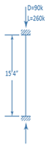
Given information:

Calculation:
Assume
Try the web size
Effective slenderness ratio is given by
Check for slenderness ratio
Nominal compressive strength is given by
Check for web buckling from dimensions and properties table in the manual the width thickness ratio of the web is given by
From the AISC section we have the equation
Since
Local buckling should be checked
Width of the web is given by
Effective width is given by
Calculate effective area
Critical stress is given by
Calculate the critical buckling stress as below
Calculate nominal compressive strength of column
Try the web size
Effective slenderness ratio is given by
Calculate buckling stress
Calculate nominal compressive strength of column
Check for web buckling from dimensions and properties table in the manual the width thickness ratio of the web is given by
From the AISC section we have the equation
Since
Local buckling should be checked
Width of the web is given by
Effective width is given by
Calculate effective area
Critical stress is given by,
Calculate the critical buckling stress as below
Calculate nominal compressive strength of column
Try the web size
Conclusion:
Therefore, size
(b)
Select a
Answer to Problem 4.6.9P
Explanation of Solution
Given information:
Calculation:
Assume
Try the web size
Effective slenderness ratio is given by
Check for slenderness ratio
Check for web buckling from dimensions and properties table in the manual the width thickness ratio of the web is given by
From the AISC section we have the equation
Since,
Local buckling should be checked
Width of the web is given by
Effective width is given by
Calculate effective area
Critical stress is given by
Calculate the critical buckling stress as below
Calculate nominal compressive strength of column
Conclusion:
Therefore, size
Want to see more full solutions like this?
Chapter 4 Solutions
Steel Design (Activate Learning with these NEW titles from Engineering!)

- find SFD and BMDarrow_forwardThe data needed to answer this question is given by this link: https://docs.google.com/spreadsheets/d/1vzb03U7Uvzm7X-by3OchQNwYeREzbP6Z-xzZMP2tzNw/edit?usp=sharing if it is easier to make a copy of the data because it is on view only then feel free to do so.arrow_forwardThe data needed to answer this question is given in the following link (file is on view only so if you would like to make a copy to make it easier for yourself feel free to do so) https://docs.google.com/spreadsheets/d/1aV5rsxdNjHnkeTkm5VqHzBXZgW-Ptbs3vqwk0SYiQPo/edit?usp=sharingarrow_forward
- The benchmark is 00.00. The backsights are 6.00, 9.32 and 13.75 and 14.00 The foresights are 6.00, 9.00 and 3.22. What is the height of the instrument? H.I. - 100.00 - 124.85 - 43.07- 24.85arrow_forwardThe benchmark is 100.00. The backsights are 4.00, 6.32 and 12.75. The foresights are 6.00, 9.00 and 3.22. What is the elevation of the point? - 95.14 - 123.08 - 104.85 - 81.78arrow_forwardDetermine the stiffness matirx of the entire truss in Global co-ordinate system, clearly indicate the degrees of freedom numbers in the stiffness matrix.arrow_forward
- Determine the stiffness matrices of elements 2, 3 and 4 in the global co-ordinate system. Assume A=0.0015m2 and E=200GPa, indicate the degrees of freedom in all stiffness matricies.arrow_forwardA short plain concrete column with cross-section dimensions of 12 in x 12 in is to be constructed. If the compressive strength of the concrete (f’c) is 5000 psi, what is the maximum load that can be safely applied to the column? - 600 k - 950 k - 720 k - 347 karrow_forwardThe borrow pit has 2000 cyds of suitable fill. The fill required for the project is 1900 cyds. The swell factor is 10% and the shrinkage factor is 15%. How much more borrow do we need? Or is there extra? - 13 yards extra - 13 yards short - 200 yards extra - 161 yards shortarrow_forward
 Steel Design (Activate Learning with these NEW ti...Civil EngineeringISBN:9781337094740Author:Segui, William T.Publisher:Cengage Learning