
ANALYSIS+DESIGN OF LINEAR CIRCUITS(LL)
8th Edition
ISBN: 9781119235385
Author: Thomas
Publisher: WILEY
expand_more
expand_more
format_list_bulleted
Concept explainers
Videos
Textbook Question
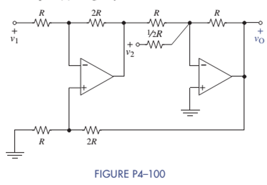
Chapter 4, Problem 4.100IP
OP AMP Circuit Analysis and Design
- Find the input-output relationship of the circuit in Figure P4-100.
- Design a circuit that realizes the relationship found in part (a) using only
Expert Solution & Answer
Want to see the full answer?
Check out a sample textbook solution
Students have asked these similar questions
6) For each independent source in this circuit calculate
the amount of power being supplied or the amount of
power being absorbed
+
6V
www
+3V-
www
20
ми
ми
352
0.5A
+
3V
In this experiment, we are going to use a 2N3904 BJT. Examine the data sheet for this device
carefully. In particular, make a note of the current gain (identified by hFE).
1. Obtain the curve trace for a "Darlington Pair" of Bipolar Junction Transistors. A Darlington
Pair consists of two transistors with the first BJT driving the base terminal of the second
transistor as shown in Figure 1 below.
A. Set up the primary sweep voltages for V1 the same as shown in the lecture notes (see
the Darlington pair IV curve).
B. Set up the secondary sweep currents for 11 to be an order of magnitude smaller than
for the single BJT. In the Sweep Type box choose linear and enter the following 3
values: Start Value: 0, End Value: 8u and Increment: 1u (see lecture notes).
C. Describe the primary differences you observe between the single BJT Curve Trace and
that of the Darlington Pair. Discuss what might cause each difference.
Q1
11
Q2
V1
Q2N3904
Figure 1. A Darlington Pair of 2N3904 transistors in a…
2. Using the IV plots shown in Fig. 3 (and found in the reintroduction to PSpice) design a BJT
biasing circuit that results in the following parameters: VCE = 2 Vand ig = 40 μA. We
also require the power supply to be fixed at 5 Volts (this is where the load line intercepts
the iB =ic = 0 line). You may use the circuit shown in Example 1. Note that all resistor
values in Example 1 must be recalculated. Your solution for the base to ground and base
to collector resistors may not be unique.
Chapter 4 Solutions
ANALYSIS+DESIGN OF LINEAR CIRCUITS(LL)
Ch. 4 - Find the voltage gain vO/vS and current gain iO/ix...Ch. 4 - Prob. 4.2PCh. 4 - Prob. 4.3PCh. 4 - Prob. 4.4PCh. 4 - Find the voltage gain vO/vS in Figure P4-5.Ch. 4 - Find the voltage gain vO/vS in Figure P4-6.Ch. 4 - Find an expression for the current gain iO/iS in...Ch. 4 - Prob. 4.8PCh. 4 - Prob. 4.9PCh. 4 - Find an expression for the voltage gain vO/vs in...
Ch. 4 - Prob. 4.12PCh. 4 - In the circuit of Figure P4-13, the VCVS has of...Ch. 4 - Prob. 4.14PCh. 4 - (a) Find the Thévenin equivalent circuit that the...Ch. 4 - Prob. 4.16PCh. 4 - Prob. 4.18PCh. 4 - Prob. 4.19PCh. 4 - The circuit parameters in figure P4-21 are...Ch. 4 - The circuit parameters in Figure P4-21 are...Ch. 4 - The parameters of the transistor in Figure P4-23...Ch. 4 - Prob. 4.25PCh. 4 - Find the voltage gain of each OP AMP circuit shown...Ch. 4 - Considering simplicity and standard 10 tolerance...Ch. 4 - Two OP AMP circuits are shown in Figure P4-28....Ch. 4 - Prob. 4.29PCh. 4 - What is the range of the gain vO/vS in Figure...Ch. 4 - Using only one OP AMP, design a circuit that...Ch. 4 - Design a circuit using only one OP AMP that...Ch. 4 - Prob. 4.36PCh. 4 - For the circuit in Figure P4-37: (a) Find vO in...Ch. 4 - A young designer needed to amplify a 2-V signal by...Ch. 4 - Design two circuits to produce the following...Ch. 4 - Design a noninverting summer for five inputs with...Ch. 4 - For the circuit in Figure P4-41: Find vO in terms...Ch. 4 - The input-output relationship for a three-input...Ch. 4 - Find vo in terms of the inputs v1,v2, and v3 in...Ch. 4 - Prob. 4.44PCh. 4 - Prob. 4.45PCh. 4 - Prob. 4.46PCh. 4 - Prob. 4.47PCh. 4 - It is claimed that vO=vS when the switch is closed...Ch. 4 - Prob. 4.49PCh. 4 - Prob. 4.50PCh. 4 - Use node-voltage analysis in Figure P4-51 to show...Ch. 4 - Prob. 4.52PCh. 4 - Prob. 4.53PCh. 4 - For the block diagram of Figure P4-54: Find an...Ch. 4 - For the block diagram of Figure P4-55: Find an...Ch. 4 - For the circuit in Figure P4-56: Find vO in terms...Ch. 4 - Prob. 4.57PCh. 4 - Onan exam, students were asked to design an...Ch. 4 - Prob. 4.59PCh. 4 - For the circuit of Figure P4-60: Use node-voltage...Ch. 4 - Prob. 4.61PCh. 4 - Design a single OP AMP amplifier with a voltage...Ch. 4 - Design an OP AMP amplifier with a voltage gain of...Ch. 4 - Using a single OP AMP, design a circuit with...Ch. 4 - Design a differential amplifier with inputs v1 and...Ch. 4 - Using no more than two OP AMPs, design an OP AMP...Ch. 4 - Design a two-input noninverting summer that will...Ch. 4 - Design a three-input noninverting summer that will...Ch. 4 - Design a cascaded OP AMP circuit that will produce...Ch. 4 - Design a cascaded OP AMP circuit that will produce...Ch. 4 - Using the instrumentation amplifier shown in...Ch. 4 - Prob. 4.73PCh. 4 - Design a circuit that can produce vO=2000vTR2.6V...Ch. 4 - A requirement exists for an OP AMP circuit with...Ch. 4 - A requirement exists for an OP AMP circuit to...Ch. 4 - A particular application requires that an...Ch. 4 - Prob. 4.78PCh. 4 - The full-scale output of a six-bit DAC is 10.0 V....Ch. 4 - An R2R DAC is shown in Figure P4-80. The digital...Ch. 4 - A fifth bit is added to the R-2R DAC shown in...Ch. 4 - Prob. 4.82PCh. 4 - Prob. 4.83PCh. 4 - A small pressure transducer has the...Ch. 4 - A medical grade pressure transducer has been...Ch. 4 - The acid/alkaline balance of a fluid is measured...Ch. 4 - A photoresistor varies from 10 in bright sunlight...Ch. 4 - Your engineering firm needs an instrumentation...Ch. 4 - Prob. 4.90PCh. 4 - Prob. 4.92PCh. 4 - Prob. 4.93PCh. 4 - A five-bit flash ADC in Figure P4-94 uses a...Ch. 4 - Bipolar Power Supply Voltages The circuit in...Ch. 4 - Thermometer Design Problem There is a need to...Ch. 4 - High Bias Design Problem A particular pressure...Ch. 4 - Prob. 4.99IPCh. 4 - OP AMP Circuit Analysis and Design Find the...Ch. 4 - Instrumentation Amplifier with Alarm Strain gauges...
Knowledge Booster


Learn more about
Need a deep-dive on the concept behind this application? Look no further. Learn more about this topic, electrical-engineering and related others by exploring similar questions and additional content below.Similar questions
- A circuit is given as shown. (a) Find and label the circuit nodes. (6) Determine I, I₁, I2 and V₂ I₂ +1 I 12V ww 22 2 ти + 보통 162 - ти 4 52 12 50 602 I 1 Mwarrow_forwarda) A silicon wafer is uniformly doped p-type with NA=10¹³/cm³. At T=0K, what are the equilibrium hole and electron concentrations?arrow_forward1016 1015 Ge 101 Si 1013 1012 GaAs 10" (( uວ) uot¤ງແລ້ວuo ວາ.ຂ ວາsuuuT 0101 601 801 107 10% Determine the equilibrium electron and hole concentrations inside a uniformly doped sample of Si under the following conditions. (n; =1010/cm³ at 300K) a) T 300 K, NA << ND, ND = 1015/cm³ b) T 300 K, NA = 9X10¹⁵/cm³, ND = 1016/cm³ c) T = 450 K, NA = 0, ND = 1014/cm³ d) T = 650 K, NA = 0, ND = 1014/cm³ 10° 200 300 400 500 600 700 T(K)arrow_forward
- b) A semiconductor is doped with an impurity concentration N such that N >> n; and all the impurities are ionized. Also, n = N and p = n2/N. Is the impurity a donor or an acceptor? Explain.arrow_forwardd) For a silicon sample maintained at T=300K, the Fermi level is located 0.259 eV above the intrinsic Fermi level. What are the hole and electron concentrations?arrow_forwarde) In a nondegenerate germanium sample maintained under equilibrium conditions near room temperature, it is known that n=10¹³/cm³, n = 2p, and NA 0. Determine n and ND.arrow_forward
- Solve fo the voltage across the 1kohm resistor using superposition for the three following cases: only V1 present, only V2 present, and both V1 and V2 present.arrow_forwardSemiconductor A has a band gap of 1eV, while semiconductor B has a band gap of 2eV. What is the ration of the intrinsic carrier concentrations in the two materials (n₁A/NB) at 300 K. Assume any differences in the carrier effective masses may be neglected.arrow_forwardc) The electron concentration in a piece of Si maintained at 300K under equilibrium conditions is 105/cm³. What is the hole concentration?arrow_forward
- 5. Represent the following system in state-space form. Write A, B, C and D clearly in your answer. d³y d²y dt3 - +5y=2u dt²arrow_forward3. Find the transfer function H(s) and frequency response H (w) of the following system whose differential equation is given by d¹y d³y +3. dy +5 dt4 dt3 dt - d²u du 4y = - 5 dt² dtarrow_forward1. Consider a plant that you want to control. The input u(t) and output y(t) of the plant are related by y(t) = 7 u(t) + w(t) where w(t) is an additive disturbance at the output which is bounded by -0.5 w(t) ≤0.5 for all time t. You want to build a controller so that the output follows a constant reference signal r(t) = where -15 ≤≤ 15. You will consider both open-loop and closed-loop for this problem. a) Sketch the block diagram of the plant. b) Please build an open-loop controller that sets the output to 7, assuming the disturbance is ignored. Please show your controller both as an equation and a block diagram. c) Say that you use the open-loop controller in part b, but now the disturbance w(t) is present. What is the maximum possible magnitude of error in the output for the reference signal? Suppose you have designed a feedback control for the plant where the controller has the form u(t) = K(r(t) − y(t)). Here K is the gain constant of the controller that you will design. d) Please…arrow_forward
arrow_back_ios
SEE MORE QUESTIONS
arrow_forward_ios
Recommended textbooks for you
 Introductory Circuit Analysis (13th Edition)Electrical EngineeringISBN:9780133923605Author:Robert L. BoylestadPublisher:PEARSON
 Delmar's Standard Textbook Of ElectricityElectrical EngineeringISBN:9781337900348Author:Stephen L. HermanPublisher:Cengage Learning
 Programmable Logic ControllersElectrical EngineeringISBN:9780073373843Author:Frank D. PetruzellaPublisher:McGraw-Hill Education
 Fundamentals of Electric CircuitsElectrical EngineeringISBN:9780078028229Author:Charles K Alexander, Matthew SadikuPublisher:McGraw-Hill Education
 Electric Circuits. (11th Edition)Electrical EngineeringISBN:9780134746968Author:James W. Nilsson, Susan RiedelPublisher:PEARSON
 Engineering ElectromagneticsElectrical EngineeringISBN:9780078028151Author:Hayt, William H. (william Hart), Jr, BUCK, John A.Publisher:Mcgraw-hill Education,
Introductory Circuit Analysis (13th Edition)
Electrical Engineering
ISBN:9780133923605
Author:Robert L. Boylestad
Publisher:PEARSON
Delmar's Standard Textbook Of Electricity
Electrical Engineering
ISBN:9781337900348
Author:Stephen L. Herman
Publisher:Cengage Learning
Programmable Logic Controllers
Electrical Engineering
ISBN:9780073373843
Author:Frank D. Petruzella
Publisher:McGraw-Hill Education
Fundamentals of Electric Circuits
Electrical Engineering
ISBN:9780078028229
Author:Charles K Alexander, Matthew Sadiku
Publisher:McGraw-Hill Education
Electric Circuits. (11th Edition)
Electrical Engineering
ISBN:9780134746968
Author:James W. Nilsson, Susan Riedel
Publisher:PEARSON
Engineering Electromagnetics
Electrical Engineering
ISBN:9780078028151
Author:Hayt, William H. (william Hart), Jr, BUCK, John A.
Publisher:Mcgraw-hill Education,
Electrical Engineering: Ch 5: Operational Amp (2 of 28) Inverting Amplifier-Basic Operation; Author: Michel van Biezen;https://www.youtube.com/watch?v=x2xxOKOTwM4;License: Standard YouTube License, CC-BY