Concept explainers
Videos
Suppose the single slit in Figure 38.4 is 6.00 cm wide and in front of a microwave source operating at 7.50 GHz. (a) Calculate the angle for the first minimum in the diffraction pattern. (b) What is the relative intensity l/lmax at 0 =- 15.0°? (c) Assume two such sources, separated laterally by 20.0 cm, are behind the slit. What must be the maximum distance between the plane of the sources and the slit if the diffraction patterns are to be resolved? In this case, the approximation sin θ ≈ tan 8 is not valid because of the relatively small value of a/λ.
(a)
The angle for the first minimum in the diffraction pattern.
Answer to Problem 38.77CP
The angle for the first minimum in the diffraction pattern is
Explanation of Solution
Given info: The width of the slit is
The expression of wavelength (
Here,
Substitute
Thus, the wavelength of the microwave source is
The expression of the condition for the first minimum in the diffraction pattern is,
Here,
Substitute
Thus, the angle for the first minimum in the diffraction pattern is
Conclusion:
Therefore, the angle for the first minimum in the diffraction pattern is
(b)
The relative intensity at
Answer to Problem 38.77CP
The relative intensity at
Explanation of Solution
Given info: The width of the slit is
The expression of the intensity variation in a diffraction pattern from a single slit is,
Here,
Rearrange the above equation for
Substitute
Thus, the relative intensity
Conclusion
Therefore, the relative intensity at
(c)
The maximum distance between the plane of the sources and the slit if the diffraction pattern are to be resolved.
Answer to Problem 38.77CP
The maximum distance between the plane of the sources and the slit if the diffraction pattern are to be resolved is
Explanation of Solution
Given info: The width of the slit is
The figure1 shows the given condition.
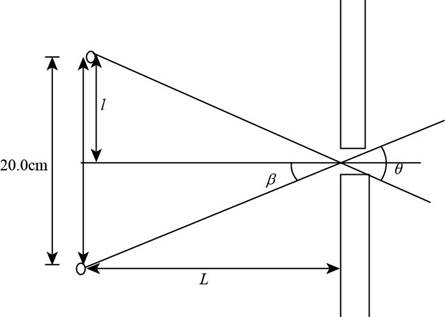
Figure (1)
Consider
The expression of distance (
Here,
Substitute
Thus, the distance of each source from the central line is
From figure1 the expression of distance (
The value of angle
Substitute
Substitute
Conclusion:
Therefore, The maximum distance between the plane of the sources and the slit if the diffraction pattern are to be resolved is
Want to see more full solutions like this?
Chapter 38 Solutions
PHYSICS 1250 PACKAGE >CI<


- Please solve this problem correctly please and be sure to provide explanation on each step so I can understand what's been done thank you. (preferrably type out everything)arrow_forwardUse a calculation to determine how far the fishing boat is from the water level .Determine distance Yarrow_forwardNo chatgpt pls will upvote Already got wrong chatgpt answerarrow_forward
- 2. 1. Tube Rating Charts Name: Directions: For the given information state if the technique is safe or unsafe and why. 60 Hertz Stator Operation Effective Focal Spot Size- 0.6 mm Peak Kilovolts MA 2 150 140 130 120 110 100 90 80 70 2501 60 50 40 30 .01 .02 .04.06 .1 .2 .4.6 1 8 10 Maximum Exposure Time In Seconds Is an exposure of 80 kVp, 0.1 second and 200 mA within the limits of the single phase, 0.6 mm focal spot tube rating chart above? Is an exposure of 100 kVp, 0.9 second and 150 mA within the limits of the single phase, 0.6 mm focal spot tube rating chart above?arrow_forwardQ: You have a CO2 laser resonator (λ = 10.6 μm). It has two curved mirrors with R₁=10m, R2= 8m, and mirror separation /= 5m. Find: R2-10 m tl Z-O 12 R1-8 m 1. Confocal parameter. b= 21w2/2 =√1 (R1-1)(R2-1)(R1+R2-21)/R1+R2-21) 2. Beam waist at t₁ & t2- 3. Waist radius (wo). 4. 5. The radius of the laser beam outside the resonator and about 0.5m from R₂- Divergence angle. 6. Radius of curvature for phase front on the mirrors R₁ & R2-arrow_forwardNo chatgpt pls will upvotearrow_forward
 University Physics Volume 3PhysicsISBN:9781938168185Author:William Moebs, Jeff SannyPublisher:OpenStax
 Physics for Scientists and Engineers: Foundations...PhysicsISBN:9781133939146Author:Katz, Debora M.Publisher:Cengage Learning
 Principles of Physics: A Calculus-Based TextPhysicsISBN:9781133104261Author:Raymond A. Serway, John W. JewettPublisher:Cengage Learning
 Glencoe Physics: Principles and Problems, Student...PhysicsISBN:9780078807213Author:Paul W. ZitzewitzPublisher:Glencoe/McGraw-Hill
 College PhysicsPhysicsISBN:9781285737027Author:Raymond A. Serway, Chris VuillePublisher:Cengage Learning