
Engineering Mechanics: Statics
8th Edition
ISBN: 9781118807330
Author: James L. Meriam, L. G. Kraige, J. N. Bolton
Publisher: WILEY
expand_more
expand_more
format_list_bulleted
Concept explainers
Videos
Textbook Question
Chapter 3.4, Problem 87P
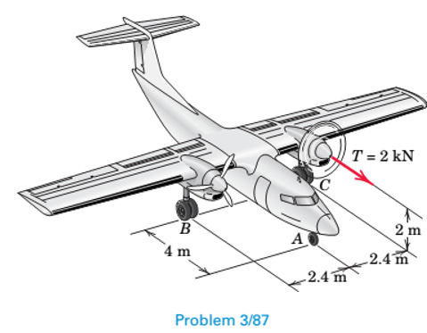
During a test, the left engine of the twin-engine air-plane is revved up and a 2-kN thrust is generated. The main wheels at B and C are braked in order to prevent motion. Determine the change (compared with the nominal values with both engines off) in the normal reaction forces at A, B, and C.
Expert Solution & Answer
Want to see the full answer?
Check out a sample textbook solution
Students have asked these similar questions
The gears shown in the figure have a diametral pitch of 2 teeth per inch and a 20° pressure angle.
The pinion rotates at 1800 rev/min clockwise and transmits 200 hp through the idler pair to gear
5 on shaft c. What forces do gears 3 and 4 transmit to the idler shaft?
TS
I
y
18T
32T
This
a
12
x
18T
C
48T
5
Question 1. Draw 3 teeth for the following pinion and gear respectively. The teeth
should be drawn near the pressure line so that the teeth from the pinion should
mesh those of the gear. Drawing scale (1:1). Either a precise hand drawing or
CAD drawing is acceptable. Draw all the trajectories of the involute lines and the
circles.
Specification: 18tooth pinion and 30tooth gear. Diameter pitch=P=6 teeth /inch.
Pressure angle:20°, 1/P for addendum (a) and 1.25/P for dedendum (b). For fillet,
c=b-a.
5. The figure shows a gear train. There is no friction at the bearings except for the gear tooth forces.
The material of the milled gears is steel having a Brinell hardness of 170. The input shaft speed (n2)
is 800 rpm. The face width and the contact angle for all gears are 1 in and 20° respectively. In this
gear set, the endurance limit (Se) is 15 kpsi and nd (design factor) is 2.
(a) Find the revolution speed of gear 5.
(b) Determine whether each gear satisfies the design factor of 2.0 for bending fatigue.
(c) Determine whether each gear satisfies the design factor of 2.0 for surface fatigue (contact stress).
(d) According to the computation results of the questions (b) and (c), explain the possible failure
mechanisms for each gear.
N4=28
800rpm
N₁=43
N5=34
N₂=14
P(diameteral pitch)=8 for all gears
Coupled to 2.5hp motor
Chapter 3 Solutions
Engineering Mechanics: Statics
Ch. 3.3 - In the side view of a 50-lb flat-screen television...Ch. 3.3 - The mass center G of the 1400-kg rear-engine car...Ch. 3.3 - A carpenter carries a 12-lb 2-in. by 4-in. board...Ch. 3.3 - The 450-kg uniform I-beam supports the load shown....Ch. 3.3 - Determine the force P required to maintain the...Ch. 3.3 - The 20-kg homogeneous smooth sphere rests on the...Ch. 3.3 - The 600-lb drum is being hoisted by the lifting...Ch. 3.3 - If the screw B of the wood clamp is tightened so...Ch. 3.3 - Determine the reactions at A and E if P=500 N....Ch. 3.3 - What horizontal force P must a worker exert on the...
Ch. 3.3 - The 20-kg uniform rectangular plate is supported...Ch. 3.3 - The 500-kg uniform beam is subjected to the three...Ch. 3.3 - A former student of mechanics wishes to weigh...Ch. 3.3 - The uniform rectangular body of mass m is placed...Ch. 3.3 - What weight WB will cause the system to be in...Ch. 3.3 - The pair of hooks is designed for the hanging of...Ch. 3.3 - The winch takes in cable at the constant rate of...Ch. 3.3 - To accommodate the rise and fall of the tide, a...Ch. 3.3 - When the 0.05-kg body is in the position shown,...Ch. 3.3 - When the 0.05-kg body is in the position shown,...Ch. 3.3 - When on level ground, the car is placed on four...Ch. 3.3 - Determine the magnitude P of the force required to...Ch. 3.3 - The 180-lb exerciser is beginning to execute some...Ch. 3.3 - Three cables are joined at the junction ring C...Ch. 3.3 - Determine the moment M which the motor must exert...Ch. 3.3 - A bicyclist applies a 40-N force to the brake...Ch. 3.3 - Find the angle of tilt with the horizontal so...Ch. 3.3 - The rack has a mass m=75kg. What moment M must be...Ch. 3.3 - The elements of a wheel-height adjuster for a lawn...Ch. 3.3 - The right-angle uniform slender bar AOB has mass...Ch. 3.3 - Determine the minimum cylinder mass m1 required to...Ch. 3.3 - Cable AB passes over the small ideal pulley C...Ch. 3.3 - A pipe P is being bent by the pipe bender as...Ch. 3.3 - The small slider A is moved along the circular...Ch. 3.3 - The asymmetric simple truss is loaded as shown....Ch. 3.3 - The tailgate OBC is attached to the rear of a...Ch. 3.3 - The indicated location of the center of gravity of...Ch. 3.3 - A uniform ring of mass m and radius r carries an...Ch. 3.3 - Determine the force T required to hold the uniform...Ch. 3.3 - A block placed under the head of the claw hammer...Ch. 3.3 - The uniform slender bar of length 2r and mass m...Ch. 3.3 - The chain binder is used to secure loads of logs,...Ch. 3.3 - In a procedure to evaluate the strength of the...Ch. 3.3 - A woman is holding a 3.6-kg sphere in her hand...Ch. 3.3 - A person is performing slow arm curls with a 10-kg...Ch. 3.3 - The exercise machine is designed with a...Ch. 3.3 - For a given value m1 for the cart mass, determine...Ch. 3.3 - The device shown is used to test automobile-engine...Ch. 3.3 - The portable floor crane in the automotive shop is...Ch. 3.3 - The torsional spring of constant kT=50Nm/rad is...Ch. 3.3 - A torque (moment) of 24Nm is required to turn the...Ch. 3.3 - During an engine test on the ground, a propeller...Ch. 3.3 - To test the deflection of the uniform 200-lb beam...Ch. 3.3 - The pin A, which connects the 200-kg steel beam...Ch. 3.3 - A portion of the shifter mechanism for a manual...Ch. 3.3 - The cargo door for an airplane of circular...Ch. 3.3 - It is desired that a person be able to begin...Ch. 3.3 - Certain elements of an in-refrigerator ice-cube...Ch. 3.3 - The lumbar portion of the human spine supports the...Ch. 3.3 - Determine and plot the moment M which much be...Ch. 3.4 - A uniform steel plate 18 in. square weighing 68 lb...Ch. 3.4 - The uniform I-beam has a mass of 60 kg per meter...Ch. 3.4 - Determine the tensions in cables AB, AC, and AD.Ch. 3.4 - An 80-lb sheet of plywood rests on two small...Ch. 3.4 - The vertical and horizontal poles at the...Ch. 3.4 - The body is constructed of uniform slender rod...Ch. 3.4 - In order to make an adjustment, engineering...Ch. 3.4 - The rectangular solid is loaded by a force which...Ch. 3.4 - When on level ground, the car is placed on four...Ch. 3.4 - The uniform rectangular plate of mass m is...Ch. 3.4 - A uniform right-circular cylinder of mass m is...Ch. 3.4 - The uniform square plate is suspended by three...Ch. 3.4 - A three-legged stool is subjected to the load L as...Ch. 3.4 - The uniform slender rod of mass m is suspended by...Ch. 3.4 - One of the vertical walls supporting end B of the...Ch. 3.4 - The light right-angle boom which supports the...Ch. 3.4 - The mass center of the 30-kg door is in the center...Ch. 3.4 - The two I-beams are welded together and are...Ch. 3.4 - The 50-kg uniform triangular plate is supported by...Ch. 3.4 - The large bracket is constructed of heavy plate...Ch. 3.4 - The 800-lb tree trunk is known to have insect...Ch. 3.4 - The smooth homogeneous sphere rests in the 120...Ch. 3.4 - Determine the magnitudes of the force R and couple...Ch. 3.4 - The 25-kg rectangular access door is held in the...Ch. 3.4 - As part of a check on its design, a lower A-arm...Ch. 3.4 - The shaft, lever, and handle are welded together...Ch. 3.4 - During a test, the left engine of the twin-engine...Ch. 3.4 - The bent rod ACDB is supported by a sleeve at A...Ch. 3.4 - Turnbuckle T1 is tightened to a tension of 750 N...Ch. 3.4 - The spring of modulus k=900N/m is stretched a...Ch. 3.4 - A homogeneous door of mass m, height h, and width...Ch. 3.4 - Consider the rudder assembly of a radio-controlled...Ch. 3.4 - The upper ends of the vertical coil springs in the...Ch. 3.4 - The uniform 30- by 40-in. trap door weighs 200 lb...Ch. 3.4 - A uniform bar of length b and mass m is suspended...Ch. 3.4 - A rectangular sign over a store has a mass of 100...Ch. 3.4 - The uniform rectangular panel ABCD has a mass of...Ch. 3.4 - Determine and plot the moment M required to rotate...Ch. 3.5 - The rack for storing automobile wheels consists of...Ch. 3.5 - The positioning device locks the sliding panel C...Ch. 3.5 - The light bracket ABC is freely hinged at A and is...Ch. 3.5 - The uniform bar with end rollers weighs 60 lb and...Ch. 3.5 - The mass of the uniform right-triangular tabletop...Ch. 3.5 - The device shown in the figure is useful for...Ch. 3.5 - Magnetic tape under a tension of 10 N at D passes...Ch. 3.5 - The tool shown is used for straightening twisted...Ch. 3.5 - A freeway sign measuring 12 ft by 6 ft is...Ch. 3.5 - A slender rod of mass m1 is welded to the...Ch. 3.5 - The curved arm BC and attached cables AB and AC...Ch. 3.5 - The device shown in section can support the load L...Ch. 3.5 - A large symmetrical drum for drying sand is...Ch. 3.5 - Determine the force P required to begin rolling...Ch. 3.5 - The small tripod like stepladder is useful for...Ch. 3.5 - Each of the three uniform 1200-mm bars has a mass...Ch. 3.5 - The uniform 15-kg plate is welded to the vertical...Ch. 3.5 - A vertical force P on the foot pedal of the bell...Ch. 3.5 - The drum and shaft are welded together and have a...Ch. 3.5 - Determine and plot the tension ratio Timg required...Ch. 3.5 - Two traffic signals are attached to the 36-ft...Ch. 3.5 - The two traffic signals of Prob. 3/119 are now...Ch. 3.5 - In executing the biceps-curl exercise, the man...Ch. 3.5 - All the conditions of Prob. 3/121 are repeated...Ch. 3.5 - The basic features of a small backhoe are shown in...Ch. 3.5 - The mass center of the 1.5-kg link OC is located...Ch. 3.5 - The system of Prob. 3/60 is repeated here, but now...Ch. 3.5 - The 125-kg homogeneous rectangular solid is held...
Additional Engineering Textbook Solutions
Find more solutions based on key concepts
What are classes responsibilities?
Starting Out with Programming Logic and Design (5th Edition) (What's New in Computer Science)
The following statement subtracts 1 from x: x = x 1
Starting Out with Python (4th Edition)
ICA 8-18
You have been working to develop a new fictitious compound in the lab. Determine the amount in units o...
Thinking Like an Engineer: An Active Learning Approach (4th Edition)
The two general categories of software are ________ and ________.
Starting Out with C++ from Control Structures to Objects (9th Edition)
Determine the minimum dimension a to the nearest mm of the beam's cross section to safely support the load. The...
Mechanics of Materials (10th Edition)
Knowledge Booster


Learn more about
Need a deep-dive on the concept behind this application? Look no further. Learn more about this topic, mechanical-engineering and related others by exploring similar questions and additional content below.Similar questions
- 1. The rotating steel shaft is simply supported by bearings at points of B and C, and is driven by a spur gear at D, which has a 6-in pitch diameter. The force F from the drive gear acts at a pressure angle of 20°. The shaft transmits a torque to point A of TA =3000 lbĘ in. The shaft is machined from steel with Sy=60kpsi and Sut=80 kpsi. (1) Draw a shear force diagram and a bending moment diagram by F. According to your analysis, where is the point of interest to evaluate the safety factor among A, B, C, and D? Describe the reason. (Hint: To find F, the torque Tд is generated by the tangential force of F (i.e. Ftangential-Fcos20°) When n=2.5, K=1.8, and K₁ =1.3, determine the diameter of the shaft based on (2) static analysis using DE theory (note that fatigue stress concentration factors need to be used for this question because the loading condition is fatigue) and (3) a fatigue analysis using modified Goodman. Note) A standard diameter is not required for the questions. 10 in Darrow_forward3 N2=28 P(diametral pitch)=8 for all gears Coupled to 25 hp motor N3=34 Full depth spur gears with pressure angle=20° N₂=2000 rpm (1) Compute the circular pitch, the center-to-center distance, and base circle radii. (2) Draw the free body diagram of gear 3 and show all the forces and the torque. (3) In mounting gears, the center-to-center distance was reduced by 0.1 inch. Calculate the new values of center-to-center distance, pressure angle, base circle radii, and pitch circle diameters. (4)What is the new tangential and radial forces for gear 3? (5) Under the new center to center distance, is the contact ratio (mc) increasing or decreasing?arrow_forward2. A flat belt drive consists of two 4-ft diameter cast-iron pulleys spaced 16 ft apart. A power of 60 hp is transmitted by a pulley whose speed is 380 rev/min. Use a service factor (Ks) pf 1.1 and a design factor 1.0. The width of the polyamide A-3 belt is 6 in. Use CD=1. Answer the following questions. (1) What is the total length of the belt according to the given geometry? (2) Find the centrifugal force (Fc) applied to the belt. (3) What is the transmitted torque through the pulley system given 60hp? (4) Using the allowable tension, find the force (F₁) on the tight side. What is the tension at the loose side (F2) and the initial tension (F.)? (5) Using the forces, estimate the developed friction coefficient (f) (6) Based on the forces and the given rotational speed, rate the pulley set. In other words, what is the horse power that can be transmitted by the pulley system? (7) To reduce the applied tension on the tight side, the friction coefficient is increased to 0.75. Find out the…arrow_forward
- The tooth numbers for the gear train illustrated are N₂ = 24, N3 = 18, №4 = 30, №6 = 36, and N₁ = 54. Gear 7 is fixed. If shaft b is turned through 5 revolutions, how many turns will shaft a make? a 5 [6] barrow_forwardCE-112 please solve this problem step by step and give me the correct answerarrow_forwardCE-112 please solve this problem step by step and give me the correct answerarrow_forward
- CE-112 solve this problem step by step and give me the correct answer pleasearrow_forwardPlease do not use any AI tools to solve this question. I need a fully manual, step-by-step solution with clear explanations, as if it were done by a human tutor. No AI-generated responses, please.arrow_forwardPlease do not use any AI tools to solve this question. I need a fully manual, step-by-step solution with clear explanations, as if it were done by a human tutor. No AI-generated responses, please.arrow_forward
arrow_back_ios
SEE MORE QUESTIONS
arrow_forward_ios
Recommended textbooks for you
 International Edition---engineering Mechanics: St...Mechanical EngineeringISBN:9781305501607Author:Andrew Pytel And Jaan KiusalaasPublisher:CENGAGE L
International Edition---engineering Mechanics: St...
Mechanical Engineering
ISBN:9781305501607
Author:Andrew Pytel And Jaan Kiusalaas
Publisher:CENGAGE L
Mechanical Design (Machine Design) Clutches, Brakes and Flywheels Intro (S20 ME470 Class 15); Author: Professor Ted Diehl;https://www.youtube.com/watch?v=eMvbePrsT34;License: Standard Youtube License