
Engineering Mechanics: Statics
8th Edition
ISBN: 9781118807330
Author: James L. Meriam, L. G. Kraige, J. N. Bolton
Publisher: WILEY
expand_more
expand_more
format_list_bulleted
Concept explainers
Videos
Textbook Question
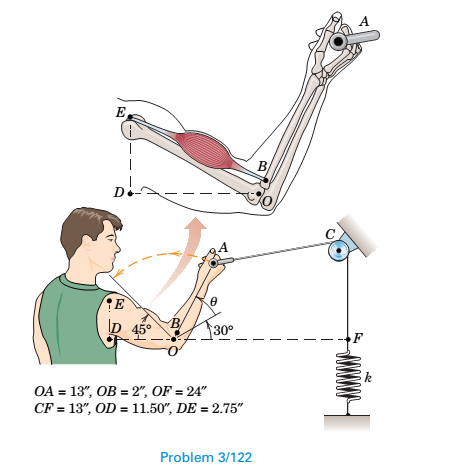
Chapter 3.5, Problem 122P
All the conditions of Prob. 3/121 are repeated here, except the weight W is replaced by a spring of constant
Expert Solution & Answer
Want to see the full answer?
Check out a sample textbook solution
Students have asked these similar questions
using the theorem of three moments, find all the moments, I need concise calculations only
Practise question need help on
Can you show explaination and working. The answer from the text book is Q=5.03 X 10^-3
Chapter 3 Solutions
Engineering Mechanics: Statics
Ch. 3.3 - In the side view of a 50-lb flat-screen television...Ch. 3.3 - The mass center G of the 1400-kg rear-engine car...Ch. 3.3 - A carpenter carries a 12-lb 2-in. by 4-in. board...Ch. 3.3 - The 450-kg uniform I-beam supports the load shown....Ch. 3.3 - Determine the force P required to maintain the...Ch. 3.3 - The 20-kg homogeneous smooth sphere rests on the...Ch. 3.3 - The 600-lb drum is being hoisted by the lifting...Ch. 3.3 - If the screw B of the wood clamp is tightened so...Ch. 3.3 - Determine the reactions at A and E if P=500 N....Ch. 3.3 - What horizontal force P must a worker exert on the...
Ch. 3.3 - The 20-kg uniform rectangular plate is supported...Ch. 3.3 - The 500-kg uniform beam is subjected to the three...Ch. 3.3 - A former student of mechanics wishes to weigh...Ch. 3.3 - The uniform rectangular body of mass m is placed...Ch. 3.3 - What weight WB will cause the system to be in...Ch. 3.3 - The pair of hooks is designed for the hanging of...Ch. 3.3 - The winch takes in cable at the constant rate of...Ch. 3.3 - To accommodate the rise and fall of the tide, a...Ch. 3.3 - When the 0.05-kg body is in the position shown,...Ch. 3.3 - When the 0.05-kg body is in the position shown,...Ch. 3.3 - When on level ground, the car is placed on four...Ch. 3.3 - Determine the magnitude P of the force required to...Ch. 3.3 - The 180-lb exerciser is beginning to execute some...Ch. 3.3 - Three cables are joined at the junction ring C...Ch. 3.3 - Determine the moment M which the motor must exert...Ch. 3.3 - A bicyclist applies a 40-N force to the brake...Ch. 3.3 - Find the angle of tilt with the horizontal so...Ch. 3.3 - The rack has a mass m=75kg. What moment M must be...Ch. 3.3 - The elements of a wheel-height adjuster for a lawn...Ch. 3.3 - The right-angle uniform slender bar AOB has mass...Ch. 3.3 - Determine the minimum cylinder mass m1 required to...Ch. 3.3 - Cable AB passes over the small ideal pulley C...Ch. 3.3 - A pipe P is being bent by the pipe bender as...Ch. 3.3 - The small slider A is moved along the circular...Ch. 3.3 - The asymmetric simple truss is loaded as shown....Ch. 3.3 - The tailgate OBC is attached to the rear of a...Ch. 3.3 - The indicated location of the center of gravity of...Ch. 3.3 - A uniform ring of mass m and radius r carries an...Ch. 3.3 - Determine the force T required to hold the uniform...Ch. 3.3 - A block placed under the head of the claw hammer...Ch. 3.3 - The uniform slender bar of length 2r and mass m...Ch. 3.3 - The chain binder is used to secure loads of logs,...Ch. 3.3 - In a procedure to evaluate the strength of the...Ch. 3.3 - A woman is holding a 3.6-kg sphere in her hand...Ch. 3.3 - A person is performing slow arm curls with a 10-kg...Ch. 3.3 - The exercise machine is designed with a...Ch. 3.3 - For a given value m1 for the cart mass, determine...Ch. 3.3 - The device shown is used to test automobile-engine...Ch. 3.3 - The portable floor crane in the automotive shop is...Ch. 3.3 - The torsional spring of constant kT=50Nm/rad is...Ch. 3.3 - A torque (moment) of 24Nm is required to turn the...Ch. 3.3 - During an engine test on the ground, a propeller...Ch. 3.3 - To test the deflection of the uniform 200-lb beam...Ch. 3.3 - The pin A, which connects the 200-kg steel beam...Ch. 3.3 - A portion of the shifter mechanism for a manual...Ch. 3.3 - The cargo door for an airplane of circular...Ch. 3.3 - It is desired that a person be able to begin...Ch. 3.3 - Certain elements of an in-refrigerator ice-cube...Ch. 3.3 - The lumbar portion of the human spine supports the...Ch. 3.3 - Determine and plot the moment M which much be...Ch. 3.4 - A uniform steel plate 18 in. square weighing 68 lb...Ch. 3.4 - The uniform I-beam has a mass of 60 kg per meter...Ch. 3.4 - Determine the tensions in cables AB, AC, and AD.Ch. 3.4 - An 80-lb sheet of plywood rests on two small...Ch. 3.4 - The vertical and horizontal poles at the...Ch. 3.4 - The body is constructed of uniform slender rod...Ch. 3.4 - In order to make an adjustment, engineering...Ch. 3.4 - The rectangular solid is loaded by a force which...Ch. 3.4 - When on level ground, the car is placed on four...Ch. 3.4 - The uniform rectangular plate of mass m is...Ch. 3.4 - A uniform right-circular cylinder of mass m is...Ch. 3.4 - The uniform square plate is suspended by three...Ch. 3.4 - A three-legged stool is subjected to the load L as...Ch. 3.4 - The uniform slender rod of mass m is suspended by...Ch. 3.4 - One of the vertical walls supporting end B of the...Ch. 3.4 - The light right-angle boom which supports the...Ch. 3.4 - The mass center of the 30-kg door is in the center...Ch. 3.4 - The two I-beams are welded together and are...Ch. 3.4 - The 50-kg uniform triangular plate is supported by...Ch. 3.4 - The large bracket is constructed of heavy plate...Ch. 3.4 - The 800-lb tree trunk is known to have insect...Ch. 3.4 - The smooth homogeneous sphere rests in the 120...Ch. 3.4 - Determine the magnitudes of the force R and couple...Ch. 3.4 - The 25-kg rectangular access door is held in the...Ch. 3.4 - As part of a check on its design, a lower A-arm...Ch. 3.4 - The shaft, lever, and handle are welded together...Ch. 3.4 - During a test, the left engine of the twin-engine...Ch. 3.4 - The bent rod ACDB is supported by a sleeve at A...Ch. 3.4 - Turnbuckle T1 is tightened to a tension of 750 N...Ch. 3.4 - The spring of modulus k=900N/m is stretched a...Ch. 3.4 - A homogeneous door of mass m, height h, and width...Ch. 3.4 - Consider the rudder assembly of a radio-controlled...Ch. 3.4 - The upper ends of the vertical coil springs in the...Ch. 3.4 - The uniform 30- by 40-in. trap door weighs 200 lb...Ch. 3.4 - A uniform bar of length b and mass m is suspended...Ch. 3.4 - A rectangular sign over a store has a mass of 100...Ch. 3.4 - The uniform rectangular panel ABCD has a mass of...Ch. 3.4 - Determine and plot the moment M required to rotate...Ch. 3.5 - The rack for storing automobile wheels consists of...Ch. 3.5 - The positioning device locks the sliding panel C...Ch. 3.5 - The light bracket ABC is freely hinged at A and is...Ch. 3.5 - The uniform bar with end rollers weighs 60 lb and...Ch. 3.5 - The mass of the uniform right-triangular tabletop...Ch. 3.5 - The device shown in the figure is useful for...Ch. 3.5 - Magnetic tape under a tension of 10 N at D passes...Ch. 3.5 - The tool shown is used for straightening twisted...Ch. 3.5 - A freeway sign measuring 12 ft by 6 ft is...Ch. 3.5 - A slender rod of mass m1 is welded to the...Ch. 3.5 - The curved arm BC and attached cables AB and AC...Ch. 3.5 - The device shown in section can support the load L...Ch. 3.5 - A large symmetrical drum for drying sand is...Ch. 3.5 - Determine the force P required to begin rolling...Ch. 3.5 - The small tripod like stepladder is useful for...Ch. 3.5 - Each of the three uniform 1200-mm bars has a mass...Ch. 3.5 - The uniform 15-kg plate is welded to the vertical...Ch. 3.5 - A vertical force P on the foot pedal of the bell...Ch. 3.5 - The drum and shaft are welded together and have a...Ch. 3.5 - Determine and plot the tension ratio Timg required...Ch. 3.5 - Two traffic signals are attached to the 36-ft...Ch. 3.5 - The two traffic signals of Prob. 3/119 are now...Ch. 3.5 - In executing the biceps-curl exercise, the man...Ch. 3.5 - All the conditions of Prob. 3/121 are repeated...Ch. 3.5 - The basic features of a small backhoe are shown in...Ch. 3.5 - The mass center of the 1.5-kg link OC is located...Ch. 3.5 - The system of Prob. 3/60 is repeated here, but now...Ch. 3.5 - The 125-kg homogeneous rectangular solid is held...
Knowledge Booster


Learn more about
Need a deep-dive on the concept behind this application? Look no further. Learn more about this topic, mechanical-engineering and related others by exploring similar questions and additional content below.Similar questions
- practise questionarrow_forwardCan you provide steps and an explaination on how the height value to calculate the Pressure at point B is (-5-3.5) and the solution is 86.4kPa.arrow_forwardPROBLEM 3.46 The solid cylindrical rod BC of length L = 600 mm is attached to the rigid lever AB of length a = 380 mm and to the support at C. When a 500 N force P is applied at A, design specifications require that the displacement of A not exceed 25 mm when a 500 N force P is applied at A For the material indicated determine the required diameter of the rod. Aluminium: Tall = 65 MPa, G = 27 GPa. Aarrow_forward
- Find the equivalent mass of the rocker arm assembly with respect to the x coordinate. k₁ mi m2 k₁arrow_forward2. Figure below shows a U-tube manometer open at both ends and containing a column of liquid mercury of length l and specific weight y. Considering a small displacement x of the manometer meniscus from its equilibrium position (or datum), determine the equivalent spring constant associated with the restoring force. Datum Area, Aarrow_forward1. The consequences of a head-on collision of two automobiles can be studied by considering the impact of the automobile on a barrier, as shown in figure below. Construct a mathematical model (i.e., draw the diagram) by considering the masses of the automobile body, engine, transmission, and suspension and the elasticity of the bumpers, radiator, sheet metal body, driveline, and engine mounts.arrow_forward
- 3.) 15.40 – Collar B moves up at constant velocity vB = 1.5 m/s. Rod AB has length = 1.2 m. The incline is at angle = 25°. Compute an expression for the angular velocity of rod AB, ė and the velocity of end A of the rod (✓✓) as a function of v₂,1,0,0. Then compute numerical answers for ȧ & y_ with 0 = 50°.arrow_forward2.) 15.12 The assembly shown consists of the straight rod ABC which passes through and is welded to the grectangular plate DEFH. The assembly rotates about the axis AC with a constant angular velocity of 9 rad/s. Knowing that the motion when viewed from C is counterclockwise, determine the velocity and acceleration of corner F.arrow_forward500 Q3: The attachment shown in Fig.3 is made of 1040 HR. The static force is 30 kN. Specify the weldment (give the pattern, electrode number, type of weld, length of weld, and leg size). Fig. 3 All dimension in mm 30 kN 100 (10 Marks)arrow_forward
- (read image) (answer given)arrow_forwardA cylinder and a disk are used as pulleys, as shown in the figure. Using the data given in the figure, if a body of mass m = 3 kg is released from rest after falling a height h 1.5 m, find: a) The velocity of the body. b) The angular velocity of the disk. c) The number of revolutions the cylinder has made. T₁ F Rd = 0.2 m md = 2 kg T T₂1 Rc = 0.4 m mc = 5 kg ☐ m = 3 kgarrow_forward(read image) (answer given)arrow_forward
arrow_back_ios
SEE MORE QUESTIONS
arrow_forward_ios
Recommended textbooks for you
 International Edition---engineering Mechanics: St...Mechanical EngineeringISBN:9781305501607Author:Andrew Pytel And Jaan KiusalaasPublisher:CENGAGE L
International Edition---engineering Mechanics: St...
Mechanical Engineering
ISBN:9781305501607
Author:Andrew Pytel And Jaan Kiusalaas
Publisher:CENGAGE L
Introduction To Engg Mechanics - Newton's Laws of motion - Kinetics - Kinematics; Author: EzEd Channel;https://www.youtube.com/watch?v=ksmsp9OzAsI;License: Standard YouTube License, CC-BY