
Engineering Mechanics: Statics
8th Edition
ISBN: 9781118807330
Author: James L. Meriam, L. G. Kraige, J. N. Bolton
Publisher: WILEY
expand_more
expand_more
format_list_bulleted
Concept explainers
Videos
Textbook Question
Chapter 3.3, Problem 41P
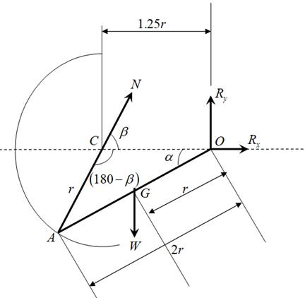
The uniform slender bar of length 2r and mass m rests against the circular surface as shown. Determine the normal force at the small roller A and the magnitude of the ideal pivot reaction at O.
Expert Solution & Answer
Want to see the full answer?
Check out a sample textbook solution
Students have asked these similar questions
this is an old practice exam, the answer is Fmin = 290.5lb but how
This is an exam review question. The answer is Pmin = 622.9 lb but why
Please do not use any AI tools to solve this question.
I need a fully manual, step-by-step solution with clear explanations, as if it were done by a human tutor.
No AI-generated responses, please.
Chapter 3 Solutions
Engineering Mechanics: Statics
Ch. 3.3 - In the side view of a 50-lb flat-screen television...Ch. 3.3 - The mass center G of the 1400-kg rear-engine car...Ch. 3.3 - A carpenter carries a 12-lb 2-in. by 4-in. board...Ch. 3.3 - The 450-kg uniform I-beam supports the load shown....Ch. 3.3 - Determine the force P required to maintain the...Ch. 3.3 - The 20-kg homogeneous smooth sphere rests on the...Ch. 3.3 - The 600-lb drum is being hoisted by the lifting...Ch. 3.3 - If the screw B of the wood clamp is tightened so...Ch. 3.3 - Determine the reactions at A and E if P=500 N....Ch. 3.3 - What horizontal force P must a worker exert on the...
Ch. 3.3 - The 20-kg uniform rectangular plate is supported...Ch. 3.3 - The 500-kg uniform beam is subjected to the three...Ch. 3.3 - A former student of mechanics wishes to weigh...Ch. 3.3 - The uniform rectangular body of mass m is placed...Ch. 3.3 - What weight WB will cause the system to be in...Ch. 3.3 - The pair of hooks is designed for the hanging of...Ch. 3.3 - The winch takes in cable at the constant rate of...Ch. 3.3 - To accommodate the rise and fall of the tide, a...Ch. 3.3 - When the 0.05-kg body is in the position shown,...Ch. 3.3 - When the 0.05-kg body is in the position shown,...Ch. 3.3 - When on level ground, the car is placed on four...Ch. 3.3 - Determine the magnitude P of the force required to...Ch. 3.3 - The 180-lb exerciser is beginning to execute some...Ch. 3.3 - Three cables are joined at the junction ring C...Ch. 3.3 - Determine the moment M which the motor must exert...Ch. 3.3 - A bicyclist applies a 40-N force to the brake...Ch. 3.3 - Find the angle of tilt with the horizontal so...Ch. 3.3 - The rack has a mass m=75kg. What moment M must be...Ch. 3.3 - The elements of a wheel-height adjuster for a lawn...Ch. 3.3 - The right-angle uniform slender bar AOB has mass...Ch. 3.3 - Determine the minimum cylinder mass m1 required to...Ch. 3.3 - Cable AB passes over the small ideal pulley C...Ch. 3.3 - A pipe P is being bent by the pipe bender as...Ch. 3.3 - The small slider A is moved along the circular...Ch. 3.3 - The asymmetric simple truss is loaded as shown....Ch. 3.3 - The tailgate OBC is attached to the rear of a...Ch. 3.3 - The indicated location of the center of gravity of...Ch. 3.3 - A uniform ring of mass m and radius r carries an...Ch. 3.3 - Determine the force T required to hold the uniform...Ch. 3.3 - A block placed under the head of the claw hammer...Ch. 3.3 - The uniform slender bar of length 2r and mass m...Ch. 3.3 - The chain binder is used to secure loads of logs,...Ch. 3.3 - In a procedure to evaluate the strength of the...Ch. 3.3 - A woman is holding a 3.6-kg sphere in her hand...Ch. 3.3 - A person is performing slow arm curls with a 10-kg...Ch. 3.3 - The exercise machine is designed with a...Ch. 3.3 - For a given value m1 for the cart mass, determine...Ch. 3.3 - The device shown is used to test automobile-engine...Ch. 3.3 - The portable floor crane in the automotive shop is...Ch. 3.3 - The torsional spring of constant kT=50Nm/rad is...Ch. 3.3 - A torque (moment) of 24Nm is required to turn the...Ch. 3.3 - During an engine test on the ground, a propeller...Ch. 3.3 - To test the deflection of the uniform 200-lb beam...Ch. 3.3 - The pin A, which connects the 200-kg steel beam...Ch. 3.3 - A portion of the shifter mechanism for a manual...Ch. 3.3 - The cargo door for an airplane of circular...Ch. 3.3 - It is desired that a person be able to begin...Ch. 3.3 - Certain elements of an in-refrigerator ice-cube...Ch. 3.3 - The lumbar portion of the human spine supports the...Ch. 3.3 - Determine and plot the moment M which much be...Ch. 3.4 - A uniform steel plate 18 in. square weighing 68 lb...Ch. 3.4 - The uniform I-beam has a mass of 60 kg per meter...Ch. 3.4 - Determine the tensions in cables AB, AC, and AD.Ch. 3.4 - An 80-lb sheet of plywood rests on two small...Ch. 3.4 - The vertical and horizontal poles at the...Ch. 3.4 - The body is constructed of uniform slender rod...Ch. 3.4 - In order to make an adjustment, engineering...Ch. 3.4 - The rectangular solid is loaded by a force which...Ch. 3.4 - When on level ground, the car is placed on four...Ch. 3.4 - The uniform rectangular plate of mass m is...Ch. 3.4 - A uniform right-circular cylinder of mass m is...Ch. 3.4 - The uniform square plate is suspended by three...Ch. 3.4 - A three-legged stool is subjected to the load L as...Ch. 3.4 - The uniform slender rod of mass m is suspended by...Ch. 3.4 - One of the vertical walls supporting end B of the...Ch. 3.4 - The light right-angle boom which supports the...Ch. 3.4 - The mass center of the 30-kg door is in the center...Ch. 3.4 - The two I-beams are welded together and are...Ch. 3.4 - The 50-kg uniform triangular plate is supported by...Ch. 3.4 - The large bracket is constructed of heavy plate...Ch. 3.4 - The 800-lb tree trunk is known to have insect...Ch. 3.4 - The smooth homogeneous sphere rests in the 120...Ch. 3.4 - Determine the magnitudes of the force R and couple...Ch. 3.4 - The 25-kg rectangular access door is held in the...Ch. 3.4 - As part of a check on its design, a lower A-arm...Ch. 3.4 - The shaft, lever, and handle are welded together...Ch. 3.4 - During a test, the left engine of the twin-engine...Ch. 3.4 - The bent rod ACDB is supported by a sleeve at A...Ch. 3.4 - Turnbuckle T1 is tightened to a tension of 750 N...Ch. 3.4 - The spring of modulus k=900N/m is stretched a...Ch. 3.4 - A homogeneous door of mass m, height h, and width...Ch. 3.4 - Consider the rudder assembly of a radio-controlled...Ch. 3.4 - The upper ends of the vertical coil springs in the...Ch. 3.4 - The uniform 30- by 40-in. trap door weighs 200 lb...Ch. 3.4 - A uniform bar of length b and mass m is suspended...Ch. 3.4 - A rectangular sign over a store has a mass of 100...Ch. 3.4 - The uniform rectangular panel ABCD has a mass of...Ch. 3.4 - Determine and plot the moment M required to rotate...Ch. 3.5 - The rack for storing automobile wheels consists of...Ch. 3.5 - The positioning device locks the sliding panel C...Ch. 3.5 - The light bracket ABC is freely hinged at A and is...Ch. 3.5 - The uniform bar with end rollers weighs 60 lb and...Ch. 3.5 - The mass of the uniform right-triangular tabletop...Ch. 3.5 - The device shown in the figure is useful for...Ch. 3.5 - Magnetic tape under a tension of 10 N at D passes...Ch. 3.5 - The tool shown is used for straightening twisted...Ch. 3.5 - A freeway sign measuring 12 ft by 6 ft is...Ch. 3.5 - A slender rod of mass m1 is welded to the...Ch. 3.5 - The curved arm BC and attached cables AB and AC...Ch. 3.5 - The device shown in section can support the load L...Ch. 3.5 - A large symmetrical drum for drying sand is...Ch. 3.5 - Determine the force P required to begin rolling...Ch. 3.5 - The small tripod like stepladder is useful for...Ch. 3.5 - Each of the three uniform 1200-mm bars has a mass...Ch. 3.5 - The uniform 15-kg plate is welded to the vertical...Ch. 3.5 - A vertical force P on the foot pedal of the bell...Ch. 3.5 - The drum and shaft are welded together and have a...Ch. 3.5 - Determine and plot the tension ratio Timg required...Ch. 3.5 - Two traffic signals are attached to the 36-ft...Ch. 3.5 - The two traffic signals of Prob. 3/119 are now...Ch. 3.5 - In executing the biceps-curl exercise, the man...Ch. 3.5 - All the conditions of Prob. 3/121 are repeated...Ch. 3.5 - The basic features of a small backhoe are shown in...Ch. 3.5 - The mass center of the 1.5-kg link OC is located...Ch. 3.5 - The system of Prob. 3/60 is repeated here, but now...Ch. 3.5 - The 125-kg homogeneous rectangular solid is held...
Additional Engineering Textbook Solutions
Find more solutions based on key concepts
In Exercises 61 through 66, rewrite the statements using augmented assignment operators. Assume that each varia...
Introduction To Programming Using Visual Basic (11th Edition)
a. What single instruction in the Vole machine language could be used to accomplish a 5-bit right circular shif...
Computer Science: An Overview (13th Edition) (What's New in Computer Science)
Show a snippet of PHP code for disconnecting from the database. Explain the meaning of the code.
Database Concepts (8th Edition)
For the circuit shown, use the node-voltage method to find v1, v2, and i1.
How much power is delivered to the c...
Electric Circuits. (11th Edition)
What is the meaning of the following line in the program in Listing 1.1? n1 = keyboard.nextInt();
Java: An Introduction to Problem Solving and Programming (8th Edition)
17–1C A high-speed aircraft is cruising in still air. How does the temperature of air at the nose of the aircra...
Thermodynamics: An Engineering Approach
Knowledge Booster


Learn more about
Need a deep-dive on the concept behind this application? Look no further. Learn more about this topic, mechanical-engineering and related others by exploring similar questions and additional content below.Similar questions
- Please do not use any AI tools to solve this question. I need a fully manual, step-by-step solution with clear explanations, as if it were done by a human tutor. No AI-generated responses, please.arrow_forwardPlease do not use any AI tools to solve this question. I need a fully manual, step-by-step solution with clear explanations, as if it were done by a human tutor. No AI-generated responses, please.arrow_forwardThis is an old practice exam. Fce = 110lb and FBCD = 62 lb but whyarrow_forward
- Quiz/An eccentrically loaded bracket is welded to the support as shown in Figure below. The load is static. The weld size for weld w1 is h1 = 4mm, for w2 h2 = 6mm, and for w3 is h3 =6.5 mm. Determine the safety factor (S.f) for the welds. F=29 kN. Use an AWS Electrode type (E100xx). 163 mm S 133 mm 140 mm Please solve the question above I solved the question but I'm sure the answer is wrong the link : https://drive.google.com/file/d/1w5UD2EPDiaKSx3W33aj Rv0olChuXtrQx/view?usp=sharingarrow_forwardQ2: (15 Marks) A water-LiBr vapor absorption system incorporates a heat exchanger as shown in the figure. The temperatures of the evaporator, the absorber, the condenser, and the generator are 10°C, 25°C, 40°C, and 100°C respectively. The strong liquid leaving the pump is heated to 50°C in the heat exchanger. The refrigerant flow rate through the condenser is 0.12 kg/s. Calculate (i) the heat rejected in the absorber, and (ii) the COP of the cycle. Yo 8 XE-V lo 9 Pc 7 condenser 5 Qgen PG 100 Qabs Pe evaporator PRV 6 PA 10 3 generator heat exchanger 2 pump 185 absorberarrow_forwardQ5:(? Design the duct system of the figure below by using the balanced pressure method. The velocity in the duct attached to the AHU must not exceed 5m/s. The pressure loss for each diffuser is equal to 10Pa. 100CFM 100CFM 100CFM ☑ ☑ 40m AHU -16m- 8m- -12m- 57m 250CFM 40m -14m- 26m 36m ☑ 250CFMarrow_forward
- A mass of ideal gas in a closed piston-cylinder system expands from 427 °C and 16 bar following the process law, pv1.36 = Constant (p times v to the power of 1.36 equals to a constant). For the gas, initial : final pressure ratio is 4:1 and the initial gas volume is 0.14 m³. The specific heat of the gas at constant pressure, Cp = 0.987 kJ/kg-K and the specific gas constant, R = 0.267 kJ/kg.K. Determine the change in total internal energy in the gas during the expansion. Enter your numerical answer in the answer box below in KILO JOULES (not in Joules) but do not enter the units. (There is no expected number of decimal points or significant figures).arrow_forwardmy ID# 016948724. Please solve this problem step by steparrow_forwardMy ID# 016948724 please find the forces for Fx=0: fy=0: fz=0: please help me to solve this problem step by steparrow_forward
- My ID# 016948724 please solve the proble step by step find the forces fx=o: fy=0; fz=0; and find shear moment and the bending moment diagran please draw the diagram for the shear and bending momentarrow_forwardMy ID#016948724. Please help me to find the moment of inertia lx ly are a please show to solve step by stepsarrow_forwardplease solve this problem step by steparrow_forward
arrow_back_ios
SEE MORE QUESTIONS
arrow_forward_ios
Recommended textbooks for you
 International Edition---engineering Mechanics: St...Mechanical EngineeringISBN:9781305501607Author:Andrew Pytel And Jaan KiusalaasPublisher:CENGAGE L
International Edition---engineering Mechanics: St...
Mechanical Engineering
ISBN:9781305501607
Author:Andrew Pytel And Jaan Kiusalaas
Publisher:CENGAGE L
Solids: Lesson 53 - Slope and Deflection of Beams Intro; Author: Jeff Hanson;https://www.youtube.com/watch?v=I7lTq68JRmY;License: Standard YouTube License, CC-BY