
Concept explainers
Videos
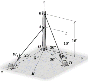
The 800-lb tree trunk is known to have insect damage near point O, so the winch arrangement shown is used to fell the tree with no cutting. If winch
Want to see the full answer?
Check out a sample textbook solution
Chapter 3 Solutions
Engineering Mechanics: Statics
Additional Engineering Textbook Solutions
Starting Out With Visual Basic (8th Edition)
Problem Solving with C++ (10th Edition)
Java How to Program, Early Objects (11th Edition) (Deitel: How to Program)
Database Concepts (8th Edition)
Computer Science: An Overview (13th Edition) (What's New in Computer Science)
Starting Out with Java: From Control Structures through Objects (7th Edition) (What's New in Computer Science)


- 3.) 15.40 – Collar B moves up at constant velocity vB = 1.5 m/s. Rod AB has length = 1.2 m. The incline is at angle = 25°. Compute an expression for the angular velocity of rod AB, ė and the velocity of end A of the rod (✓✓) as a function of v₂,1,0,0. Then compute numerical answers for ȧ & y_ with 0 = 50°.arrow_forward2.) 15.12 The assembly shown consists of the straight rod ABC which passes through and is welded to the grectangular plate DEFH. The assembly rotates about the axis AC with a constant angular velocity of 9 rad/s. Knowing that the motion when viewed from C is counterclockwise, determine the velocity and acceleration of corner F.arrow_forward500 Q3: The attachment shown in Fig.3 is made of 1040 HR. The static force is 30 kN. Specify the weldment (give the pattern, electrode number, type of weld, length of weld, and leg size). Fig. 3 All dimension in mm 30 kN 100 (10 Marks)arrow_forward
- (read image) (answer given)arrow_forwardA cylinder and a disk are used as pulleys, as shown in the figure. Using the data given in the figure, if a body of mass m = 3 kg is released from rest after falling a height h 1.5 m, find: a) The velocity of the body. b) The angular velocity of the disk. c) The number of revolutions the cylinder has made. T₁ F Rd = 0.2 m md = 2 kg T T₂1 Rc = 0.4 m mc = 5 kg ☐ m = 3 kgarrow_forward(read image) (answer given)arrow_forward
- 11-5. Compute all the dimensional changes for the steel bar when subjected to the loads shown. The proportional limit of the steel is 230 MPa. 265 kN 100 mm 600 kN 25 mm thickness X Z 600 kN 450 mm E=207×103 MPa; μ= 0.25 265 kNarrow_forwardT₁ F Rd = 0.2 m md = 2 kg T₂ Tz1 Rc = 0.4 m mc = 5 kg m = 3 kgarrow_forward2. Find a basis of solutions by the Frobenius method. Try to identify the series as expansions of known functions. (x + 2)²y" + (x + 2)y' - y = 0 ; Hint: Let: z = x+2arrow_forward
- 1. Find a power series solution in powers of x. y" - y' + x²y = 0arrow_forward3. Find a basis of solutions by the Frobenius method. Try to identify the series as expansions of known functions. 8x2y" +10xy' + (x 1)y = 0 -arrow_forwardHello I was going over the solution for this probem and I'm a bit confused on the last part. Can you please explain to me 1^4 was used for the Co of the tubular cross section? Thank you!arrow_forward
 International Edition---engineering Mechanics: St...Mechanical EngineeringISBN:9781305501607Author:Andrew Pytel And Jaan KiusalaasPublisher:CENGAGE L