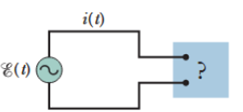
SSM WWW Figure 31-36 shows an ac generator connected to a “black box” through a pair of terminals. The box contains an RLC circuit, possibly even a multiloop circuit, whose elements and connections we do not know. Measurements outside the box reveal that

Figure 31-36 Problem 61.
ℰ(t) = (75.0 V) sin ωdt
and
i(t) = (1.20 A) sin(ωdt + 42.0°).
(a) What is the power factor? (b) Does the current lead or lag the emf? (c) Is the circuit in the box largely inductive or largely capacitive? (d) Is the circuit in the box in resonance? (e) Must there be a capacitor in the box? (f) An inductor? (g) A resistor? (h) At what average rate is energy delivered to the box by the generator? (i) Why don’t you need to know ωd to answer all these questions?
Want to see the full answer?
Check out a sample textbook solution
Chapter 31 Solutions
FUNDAMENTALS OF PHYSICS (LLF)+WILEYPLUS
Additional Science Textbook Solutions
Microbiology: An Introduction
Chemistry (7th Edition)
Fundamentals Of Thermodynamics
Organic Chemistry (8th Edition)
Chemistry: Structure and Properties (2nd Edition)
Chemistry: A Molecular Approach (4th Edition)
- Solve and answer the question correctly please. Thank you!!arrow_forwardA spiral transition curve is used on railroads to connect a straight portion of the track with a curved portion. (Figure 1) Part A v = v₁ft/s 600 ft y = (106) x³ If the spiral is defined by the equation y = (106)³, where x and y are in feet, determine the magnitude of the acceleration of a train engine moving with a constant speed of v₁ = 30 ft/s when it is at point x = 600 ft. Express your answer to three significant figures and include the appropriate units. ? a = Value Unitsarrow_forwardsolve and answer the problem correctly please. Thank you!!arrow_forward
- Solve and answer the question correctly please. Thank you!!arrow_forwardSolve and answer the question correctly please. Thank you!!arrow_forwardWhen the motorcyclist is at A, he increases his speed along the vertical circular path at the rate of = (0.3t) ft/s², where t is in seconds. Take p = 360 ft. (Figure 1) Part A 60° Ρ B If he starts from rest at A, determine the magnitude of his velocity when he reaches B. Express your answer to three significant figures and include the appropriate units. v = Value Submit Request Answer ་ Part B ? Units If he starts from rest at A, determine the magnitude of his acceleration when he reaches B. Express your answer to three significant figures and include the appropriate units. 11 ? a = Value Unitsarrow_forward
- The car starts from rest at s = 0 and increases its speed at a₁ = 7 m/s². (Figure 1) Part A = 40 m Determine the time when the magnitude of acceleration becomes 20 m/s². Express your answer to three significant figures and include the appropriate units. ? t = Value Units Part B At what position s does this occur? Express your answer to three significant figures and include the appropriate units. s = Value Submit Request Answer ? Unitsarrow_forwardSolve and answer the question correctly please. Thank you!!arrow_forwardSolve and answer the question correctly please. Thank you!!arrow_forward
- Solve and answer the question correctly please. Thank you!!arrow_forwardSolve and answer the question correctly please. Thank you!!arrow_forwardr 2. Measuring Length mm 1 cm 2 3 INCH 1 16THS 5 6 7 8 9 10 11 FAIRGATE COLD SPRING, NEW YORK 2 3 12 1. Using the metric (top) scale only, what units are being used for the long lines with the numbers? Hint: Remember that 2.54 cm = 1 in. 2. What are the units of the small lines? 3. How many decimal places should be recorded using this tool? 4. What is the length of the red line? Note: Make sure to use the correct units and decimal places. 5. Now observe your ruler. What metric units are used on your ruler? 6. How many decimal places should you record when using your ruler? 7. Measure a box, book, coin and can and fill out the data table below. Make sure to use units and the correct number of decimal places for your ruler. Table 1: Measuring Length Data Table Object Length of the box Length Local PR Distribution Only $99/Release. Get Started On Our Website Now! V 2 217arrow_forward
 Physics for Scientists and EngineersPhysicsISBN:9781337553278Author:Raymond A. Serway, John W. JewettPublisher:Cengage Learning
 Physics for Scientists and Engineers with Modern ...PhysicsISBN:9781337553292Author:Raymond A. Serway, John W. JewettPublisher:Cengage Learning
 College PhysicsPhysicsISBN:9781305952300Author:Raymond A. Serway, Chris VuillePublisher:Cengage Learning
 College PhysicsPhysicsISBN:9781285737027Author:Raymond A. Serway, Chris VuillePublisher:Cengage Learning
 Physics for Scientists and Engineers: Foundations...PhysicsISBN:9781133939146Author:Katz, Debora M.Publisher:Cengage Learning


