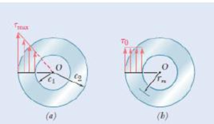

Fig. P3.29
3.29 While the exact distribution of the shearing stresses in a hollow-cylindrical shaft is as shown in Fig. P3.29a, an approximate value can be obtained for
Want to see the full answer?
Check out a sample textbook solution
Chapter 3 Solutions
EBK MECHANICS OF MATERIALS
- Can you solve it analytically using laplace transforms and with Matlab code as well please. Thank You.arrow_forwardQ11. Determine the magnitude of the reaction force at C. 1.5 m a) 4 KN D b) 6.5 kN c) 8 kN d) e) 11.3 KN 20 kN -1.5 m- C 4 kN -1.5 m B Mechanical engineering, No Chatgpt.arrow_forwardplease help with this practice problem(not a graded assignment, this is a practice exam), and please explain how to use sohcahtoaarrow_forward
- Solve this problem and show all of the workarrow_forwardSolve this problem and show all of the workarrow_forwardaversity of Baoyion aculty of Engineering-AIMusyab Automobile Eng. Dep. Year: 2022-2023, st Course, 1st Attempt Stage: 3rd Subject: Heat Transfer I Date: 2023\01\23- Monday Time: 3 Hours Q4: A thick slab of copper initially at a uniform temperature of 20°C is suddenly exposed to radiation at one surface such that the net heat flux is maintained at a constant value of 3×10⁵ W/m². Using the explicit finite-difference techniques with a space increment of Ax = = 75 mm, determine the temperature at the irradiated surface and at an interior point that is 150 mm from the surface after 2 min have elapsed. Q5: (12.5 M) A) A steel bar 2.5 cm square and 7.5 cm long is initially at a temperature of 250°C. It is immersed in a tank of oil maintained at 30°C. The heat-transfer coefficient is 570 W/m². C. Calculate the temperature in the center of the bar after 3 min. B) Air at 90°C and atmospheric pressure flows over a horizontal flat plate at 60 m/s. The plate is 60 cm square and is maintained at a…arrow_forward
- University of Baby on Faculty of Engineering-AIMusyab Automobile Eng. Dep. Year: 2022-2023. 1 Course, 1" Attempt Stage 3 Subject Heat Transfer I Date: 2023 01 23- Monday Time: 3 Hours Notes: Q1: • • Answer four questions only Use Troles and Appendices A) A flat wall is exposed to an environmental temperature of 38°C. The wall is covered with a layer of insulation 2.5 cm thick whose thermal conductivity is 1.4 W/m. C, and the temperature of the wall on the inside of the insulation is 315°C. The wall loses heat to the environment by convection. Compute the value of the convection heat-transfer coefficient that must be maintained on the outer surface of the insulation to ensure that the outer-surface temperature does not exceed 41°C. B) A vertical square plate, 30 cm on a side, is maintained at 50°C and exposed to room air at 20°C. The surface emissivity is 0.8. Calculate the total heat lost by both sides of the plate. (12.5 M) Q2: An aluminum fin 1.5 mm thick is placed on a circular tube…arrow_forwardSolve using graphical method and analytical method, only expert should solvearrow_forwardSolve this and show all of the workarrow_forward
 Elements Of ElectromagneticsMechanical EngineeringISBN:9780190698614Author:Sadiku, Matthew N. O.Publisher:Oxford University Press
 Mechanics of Materials (10th Edition)Mechanical EngineeringISBN:9780134319650Author:Russell C. HibbelerPublisher:PEARSON
 Thermodynamics: An Engineering ApproachMechanical EngineeringISBN:9781259822674Author:Yunus A. Cengel Dr., Michael A. BolesPublisher:McGraw-Hill Education
 Control Systems EngineeringMechanical EngineeringISBN:9781118170519Author:Norman S. NisePublisher:WILEY
 Mechanics of Materials (MindTap Course List)Mechanical EngineeringISBN:9781337093347Author:Barry J. Goodno, James M. GerePublisher:Cengage Learning
 Engineering Mechanics: StaticsMechanical EngineeringISBN:9781118807330Author:James L. Meriam, L. G. Kraige, J. N. BoltonPublisher:WILEY


