
Concept explainers
Videos
For the circuit shown in Fig. 3.113, write the node-voltage equations by inspection.
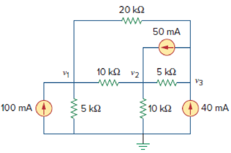
Figure 3.113
For Prob. 3.69.
Write the node-voltage equations for the circuit in Figure 3.113.
Answer to Problem 69P
The matrix form representation of node-voltage equations for the given circuit is
Explanation of Solution
Given data:
Refer to Figure 3.113 in the textbook for the nodal analysis.
Calculation:
Apply Kirchhoff’s current law at node
Simplify the equation as follows.
Apply Kirchhoff’s current law at node
Simplify the equation as follows.
Apply Kirchhoff’s current law at node
Simplify the equation as follows.
Represent the equations (1), (2), and (3) in matrix form.
Conclusion:
Thus, the matrix form representation of node-voltage equations for the given circuit is
Want to see more full solutions like this?
Chapter 3 Solutions
EBK FUNDAMENTALS OF ELECTRIC CIRCUITS


- I need an example on the subject (second order differential equations) and you solve it using the partition method and the Laplace method. Suggest an easy and simple example for me and solve it using two methods, only one example.arrow_forward5- Discuss your resultsarrow_forwardWrite a program to flash three LED's connected to ports (8, 9 & 10) respectively as shown below: (Note: T₁-T3-5s & T₂=3s) LED, (pin 10) 2. Suen LED₂ (pin 9) LED, (pin 8) T₁'T' T'arrow_forward
- 3- Draw the waveform for the cct. shown in fig.(2) but after replaced Di by thyristor with a 30°, 90° . 4- Draw the waveform for the cat shown in fig.(2) but after replaced D1 and D3 by thyristors with α = 30° and a2 = 90°. V₁ Det Ve DAX 뭔가 No Fig. (2)arrow_forwardWrite a program to flash three LED's connected to ports (11, 12 & 13) respectively as shown below: (Note: T-T3-3s & T₂= T₁=2s) LED (pin 11) LED2 (pin 12) LED: (pin 13) T' T2 T3' 14arrow_forwardNot use ai pleasearrow_forward
- Suppose you have three push buttons connected to (B5, B6 & B7) and eight LED's connected to (Do D7): Write a program to flash ON the odd LED's if we press the switch B7 for 0.4s, flash ON the even LED's if we press the switch (B6 for 0.4s and flash ON all the LED's if we press the switch B5 for 0.7s.arrow_forwardSuppose you have two push buttons connected to ports (0 & 1) and four LED's connected to ports (6-9). Write a program to flash ON the odd LED's if we press the switch 0 for 4s, flash ON the even LED's if we press the switch 1 for 5s and flash ON all the LED's otherwise for 6s.arrow_forward1. Figure 2 shows a filter. Transpose the filter by first converting it into a DFG and redraw the transposed filter + (✗ D + × y(n) ✗ (☑ (x) (+ 4D (×→+) D u(n) ✗ (☑ + Figure 2: Filter structure. D Darrow_forward
- Design a 4-bit circuit with 2 outputs A and B. A is 1 if the input is divisible by 2 and B is 1 if the input is divisible by 3. Simplify A and B and implement the circuit.a. Draw KMAP for A and B and simplify them and then draw circuitarrow_forwardQuestion 1. Design a 4-bit combinational circuit for a 2’s complementer. The circuit generates at the output the 2’s complement of the input binary numbers.a) Complete the following truth table. A, B, C, D indicate the input binary number to be complement- ed using 2’s complement and W, X, Y, Z represent the output 2’s complement of the input binary number. The variable D is the least significant bit and A is the most significant bit of the binary number.b) Simplify the Boolean function W in its Sum-of-Products (SOP) form using a K-Map (you do not have to show the circuit) and provide its simplified Boolean expression.c) Show that the Boolean function W can be realized using exclusive-OR (XOR) gates and OR gates draw its corresponding logic circuit.d) Simplify the Boolean function Z in its Product-of-Sums (POS) form using a K-Map, provide its simplified Boolean expression and draw its corresponding logic circuit.arrow_forwardGiven the function F(x,y,z)= y +x′za. Expand F to its Product-of-Maxterms formb. Implement F with NAND gates only.arrow_forward
 Introductory Circuit Analysis (13th Edition)Electrical EngineeringISBN:9780133923605Author:Robert L. BoylestadPublisher:PEARSON
 Delmar's Standard Textbook Of ElectricityElectrical EngineeringISBN:9781337900348Author:Stephen L. HermanPublisher:Cengage Learning
 Programmable Logic ControllersElectrical EngineeringISBN:9780073373843Author:Frank D. PetruzellaPublisher:McGraw-Hill Education
 Fundamentals of Electric CircuitsElectrical EngineeringISBN:9780078028229Author:Charles K Alexander, Matthew SadikuPublisher:McGraw-Hill Education
 Electric Circuits. (11th Edition)Electrical EngineeringISBN:9780134746968Author:James W. Nilsson, Susan RiedelPublisher:PEARSON
 Engineering ElectromagneticsElectrical EngineeringISBN:9780078028151Author:Hayt, William H. (william Hart), Jr, BUCK, John A.Publisher:Mcgraw-hill Education,