
EBK FUNDAMENTALS OF ELECTRIC CIRCUITS
6th Edition
ISBN: 8220102801448
Author: Alexander
Publisher: YUZU
expand_more
expand_more
format_list_bulleted
Concept explainers
Videos
Textbook Question
Chapter 3, Problem 87P
For the circuit in Fig. 3.123, find the gain vo/vs.
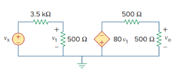
Figure 3.123
For Prob. 3.87.
Expert Solution & Answer
Want to see the full answer?
Check out a sample textbook solution
Students have asked these similar questions
functions:
where are the Cauchy-Riemann equations satisfied by the
1- w = z² - 4
2- w = 7
Z
Z+5
3- w =
Z-2
z+1
Find the integral for
ezz
Cz-i
ezz
Zdz and $c (z-i)³
dz
Determine the voltage across A and B in the circuit given below:
Chapter 3 Solutions
EBK FUNDAMENTALS OF ELECTRIC CIRCUITS
Ch. 3.2 - Figure 3.4 For Practice Prob. 3.1. Obtain the node...Ch. 3.2 - Figure 3.6 For Practice Prob. 3.2. Find the...Ch. 3.3 - Figure 3.11 For Practice Prob. 3.3. Find v and i...Ch. 3.3 - Figure 3.14 For Practice Prob. 3.4. Find v1, v2,...Ch. 3.4 - Practice Problem 3.5 Figure 3.19 For Practice...Ch. 3.4 - Practice Problem 3.6 Figure 3.21 For Practice...Ch. 3.5 - Practice Problem 3.7 Figure 3.25 For Practice...Ch. 3.6 - By inspection, obtain the node-voltage equations...Ch. 3.6 - By inspection, obtain the mesh-current equations...Ch. 3.8 - For the circuit in Fig. 3.33, use PSpice to find...
Ch. 3.8 - Use PSpice to determine currents i1, i2, and i3 in...Ch. 3.9 - For the transistor circuit in Fig. 3.42, let =...Ch. 3.9 - The transistor circuit in Fig. 3.45 has = 80 and...Ch. 3 - At node 1 in the circuit of Fig. 3.46, applying...Ch. 3 - Figure 3.46 For Review Questions 3.1 and 3.2 In...Ch. 3 - For the circuit in Fig. 3.47, v1 and v2 are...Ch. 3 - Figure 3.47 For Review Questions 3.3 and 3.4....Ch. 3 - The circuit i in the circuit of Fig. 3.48 is:...Ch. 3 - Figure 3.48 For Review Questions 3.5 and 3.6....Ch. 3 - In the circuit of Fig. 3.49, current i1 is: (a)4 A...Ch. 3 - Figure 3.49 For Review Questions 3.7 and 3.8....Ch. 3 - The PSpice part name for a current-controlled...Ch. 3 - Which of the following statements are not true of...Ch. 3 - Using Fig. 3.50, design a problem to help other...Ch. 3 - For the circuit in Fig. 3.51, obtain v1 and v2....Ch. 3 - Find the currents I1 through I4 and the voltage vo...Ch. 3 - Given the circuit in Fig. 3.53, calculate the...Ch. 3 - Obtain vo in the circuit of Fig. 3.54. Figure 3.54...Ch. 3 - Solve for V1 in the circuit of Fig. 3.55 using...Ch. 3 - Apply nodal analysis to solve for Vx in the...Ch. 3 - Using nodal analysis, find vo in the circuit of...Ch. 3 - Determine Ib in the circuit in Fig. 3.58 using...Ch. 3 - Prob. 10PCh. 3 - Find Vo and the power dissipated in all the...Ch. 3 - Using nodal analysis, determine Vo in the circuit...Ch. 3 - Calculate v1 and v2 in the circuit of Fig. 3.62...Ch. 3 - Using nodal analysis, find vo in the circuit of...Ch. 3 - Apply nodal analysis to find io and the power...Ch. 3 - Determine voltages v1 through v3 in the circuit of...Ch. 3 - Prob. 17PCh. 3 - Determine the node voltages in the circuit in Fig....Ch. 3 - Use nodal analysis to find v1, v2 and v3 in the...Ch. 3 - For the circuit in Fig. 3.69, find v1, v2, and v3...Ch. 3 - For the circuit in Fig. 3.70, find v1 and v2 using...Ch. 3 - Determine v1 and v2 in the circuit of Fig. 3.71....Ch. 3 - Use nodal analysis to find Vo in the circuit of...Ch. 3 - Use nodal analysis and MATLAB to find Vo in the...Ch. 3 - Use nodal analysis along with MATLAB to determine...Ch. 3 - Calculate the node voltages v1, v2, and v3 in the...Ch. 3 - Use nodal analysis to determine voltages v1, v2,...Ch. 3 - Use MATLAB to find the voltages at nodes a, b, c,...Ch. 3 - Use MATLAB to solve for the node voltages in the...Ch. 3 - Using nodal analysis, find vo and io in the...Ch. 3 - Find the node voltages for the circuit in Fig....Ch. 3 - Obtain the node voltages v1, v2, and v3 in the...Ch. 3 - Which of the circuits in Fig. 3.82 is planar? For...Ch. 3 - Determine which of the circuits in Fig. 3.83 is...Ch. 3 - Figure 3.54 For Prob. 3.5. Rework Prob. 3.5 using...Ch. 3 - Use mesh analysis to obtain ia, ib, and ic in the...Ch. 3 - Using nodal analysis, find vo in the circuit of...Ch. 3 - Apply mesh analysis to the circuit in Fig. 3.85...Ch. 3 - Using Fig. 3.50 from Prob. 3.1, design a problem...Ch. 3 - Prob. 40PCh. 3 - Apply mesh analysis to find i in Fig. 3.87. Figure...Ch. 3 - Using Fig. 3.88, design a problem to help students...Ch. 3 - Prob. 43PCh. 3 - Prob. 44PCh. 3 - Prob. 45PCh. 3 - Calculate the mesh currents i1 and i2 in Fig....Ch. 3 - Rework Prob. 3.19 using mesh analysis. Use nodal...Ch. 3 - Prob. 48PCh. 3 - Find vo and io in the circuit of Fig. 3.94. Figure...Ch. 3 - Prob. 50PCh. 3 - Apply mesh analysis to find vo in the circuit of...Ch. 3 - Use mesh analysis to find i1, i2 and i3 in the...Ch. 3 - Prob. 53PCh. 3 - Find the mesh currents i1, i2, and i3 in the...Ch. 3 - In the circuit of Fig. 3.100, solve for I1, I2,...Ch. 3 - Determine v1 and v2 in the circuit of Fig. 3.101....Ch. 3 - In the circuit of Fig. 3.102, find the values of...Ch. 3 - Find i1, i2, and i3 in the circuit of Fig. 3.103....Ch. 3 - Rework Prob. 3.30 using mesh analysis. Using nodal...Ch. 3 - Prob. 60PCh. 3 - Calculate the current gain iois in the circuit of...Ch. 3 - Find the mesh currents i1, i2, and i3 in the...Ch. 3 - Find vx and ix in the circuit shown in Fig. 3.107....Ch. 3 - Find vo and io in the circuit of Fig. 3.108.Ch. 3 - Use MATLAB to solve for the mesh currents in the...Ch. 3 - Write a set of mesh equations for the circuit in...Ch. 3 - Obtain the node-voltage equations for the circuit...Ch. 3 - Prob. 68PCh. 3 - For the circuit shown in Fig. 3.113, write the...Ch. 3 - Write the node-voltage equations by inspection and...Ch. 3 - Write the mesh-current equations for the circuit...Ch. 3 - Prob. 72PCh. 3 - Write the mesh-current equations for the circuit...Ch. 3 - By inspection, obtain the mesh-current equations...Ch. 3 - Use PSpice or MultiSim to solve Prob. 3.58....Ch. 3 - Use PSpice or MultiSim to solve Prob. 3.27....Ch. 3 - Solve for V1 and V2 in the circuit of Fig. 3.119...Ch. 3 - Solve Prob. 3.20 using PSpice or MultiSim. 3.20...Ch. 3 - Prob. 79PCh. 3 - Find the nodal voltages v1 through v4 in the...Ch. 3 - Use PSpice or MultiSim to solve the problem in...Ch. 3 - If the Schematics Netlist for a network is as...Ch. 3 - The following program is the Schematics Netlist of...Ch. 3 - Prob. 84PCh. 3 - An audio amplifier with a resistance of 9 ...Ch. 3 - Prob. 86PCh. 3 - For the circuit in Fig. 3.123, find the gain...Ch. 3 - Determine the gain vo/vs of the transistor...Ch. 3 - For the transistor circuit shown in Fig. 3.125,...Ch. 3 - Calculate vs for the transistor in Fig. 3.126...Ch. 3 - Prob. 91PCh. 3 - Prob. 92PCh. 3 - Rework Example 3.11 with hand calculation. In the...
Knowledge Booster


Learn more about
Need a deep-dive on the concept behind this application? Look no further. Learn more about this topic, electrical-engineering and related others by exploring similar questions and additional content below.Similar questions
- An inductive coil having negligible resistance and 0.1H inductance is connected a supply of 220V, 50 Hz. Calculate (a) Inductive reactance, (b) RMS value of Current, (c) Power consumed, (d) Power factor, (e) Write down the equations for voltage and current.arrow_forwardIf Fourier transform of f(t) is F(w) find Fourier transform of g(t) using only properties. d g(t) = f(2t)+8(3-1)+ ej(t-1)f(t) dtarrow_forward3z²+7z+1 dz (b) If C is the circle |z+i|=1. What is the value of S (a) If C is the circle |z+1|=1. z+1 (c) If C is the ellipse x²+y2=8.arrow_forward
- Please answer allarrow_forwardfind the inverse Laplace transform of X(s)= i) Re[s]> 3 ii) Re[s]<1 s+5 for (s-1)(s-2)(s-3) iii) 1arrow_forwardFor R1, what is the resistance in kΩ? For R1, what the current in mA? For R1, what is the voltage in V? For R1, what is the power in W? For R2, what is the resistance in kΩ? For R2, what the current in mA? For R2, what is the voltage in V? For R2, what is the power in W? For R3, what is the resistance in kΩ? For R3, what the current in mA? For R3, what is the voltage in V? For R3, what is the power in W? For R4, what is the resistance in kΩ? For R4, what the current in mA? For R4, what is the voltage in V? For R4, what is the power in W? For R5, what is the resistance in kΩ? For R5, what the current in mA? For R5, what is the voltage in V? For R5, what is the power in W? What is the total resistance in Ω? What is the total current in mA? What is the total voltage in V? What is the total power in W?arrow_forwardarrow_back_iosSEE MORE QUESTIONSarrow_forward_ios
Recommended textbooks for you
 Introductory Circuit Analysis (13th Edition)Electrical EngineeringISBN:9780133923605Author:Robert L. BoylestadPublisher:PEARSON
 Delmar's Standard Textbook Of ElectricityElectrical EngineeringISBN:9781337900348Author:Stephen L. HermanPublisher:Cengage Learning
 Programmable Logic ControllersElectrical EngineeringISBN:9780073373843Author:Frank D. PetruzellaPublisher:McGraw-Hill Education
 Fundamentals of Electric CircuitsElectrical EngineeringISBN:9780078028229Author:Charles K Alexander, Matthew SadikuPublisher:McGraw-Hill Education
 Electric Circuits. (11th Edition)Electrical EngineeringISBN:9780134746968Author:James W. Nilsson, Susan RiedelPublisher:PEARSON
 Engineering ElectromagneticsElectrical EngineeringISBN:9780078028151Author:Hayt, William H. (william Hart), Jr, BUCK, John A.Publisher:Mcgraw-hill Education,
Introductory Circuit Analysis (13th Edition)
Electrical Engineering
ISBN:9780133923605
Author:Robert L. Boylestad
Publisher:PEARSON
Delmar's Standard Textbook Of Electricity
Electrical Engineering
ISBN:9781337900348
Author:Stephen L. Herman
Publisher:Cengage Learning
Programmable Logic Controllers
Electrical Engineering
ISBN:9780073373843
Author:Frank D. Petruzella
Publisher:McGraw-Hill Education
Fundamentals of Electric Circuits
Electrical Engineering
ISBN:9780078028229
Author:Charles K Alexander, Matthew Sadiku
Publisher:McGraw-Hill Education
Electric Circuits. (11th Edition)
Electrical Engineering
ISBN:9780134746968
Author:James W. Nilsson, Susan Riedel
Publisher:PEARSON
Engineering Electromagnetics
Electrical Engineering
ISBN:9780078028151
Author:Hayt, William H. (william Hart), Jr, BUCK, John A.
Publisher:Mcgraw-hill Education,
Norton's Theorem and Thevenin's Theorem - Electrical Circuit Analysis; Author: The Organic Chemistry Tutor;https://www.youtube.com/watch?v=-kkvqr1wSwA;License: Standard Youtube License