
Mastering Engineering with Pearson eText -- Standalone Access Card -- for Electrical Engineering: Principles & Applications
7th Edition
ISBN: 9780134486970
Author: Allan R. Hambley
Publisher: PEARSON
expand_more
expand_more
format_list_bulleted
Videos
Textbook Question
Chapter 3, Problem 3.63P
Find the equivalent inductance for each of the series and parallel combinations shown in Figure
P3.63.
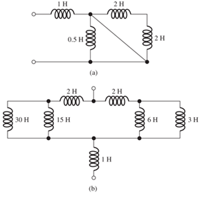
Figure P3.63
Expert Solution & Answer

Trending nowThis is a popular solution!

Students have asked these similar questions
Redraw the previous circuit and add a 24 V red lamp to indicate the relay coil is on, a 230 V yellow lamp to indicate the solenoid is on, green lamp to indicate the solenoid is off. Use only one relay, which has multiple contacts.
Design a control circuit so a 24 V relay , start button, and a stop push button (on/off with memory) operates an electromechanical relay to control a 230 V solenoid
Next, Redraw the previous circuit and add a 24 V red lamp to indicate the relay coil is on, a 230 V yellow lamp to indicate the solenoid is on, green lamp to indicate the solenoid is off. Use only one relay, which has multiple contacts.
please answer it handwritten , thanks! will give thumbs up
Chapter 3 Solutions
Mastering Engineering with Pearson eText -- Standalone Access Card -- for Electrical Engineering: Principles & Applications
Ch. 3 - What is a dielectric material? Give two examples.Ch. 3 - Briefly discuss how current can flow “through” a...Ch. 3 - What current flows through an ideal capacitor if...Ch. 3 - Describe the internal construction of capacitors.Ch. 3 - A voltage of 50 V appears across a 10F capacitor....Ch. 3 - A 2000F capacitor, initially charged to 100V, is...Ch. 3 - A 5F Capacitor ischarged to 1000 V. Determine the...Ch. 3 - The voltage across a 10F capacitor is given by v...Ch. 3 - The voltage across a 1F capacitor is given by...Ch. 3 - Prior to t = 0, a 100F capacitance is uncharged...
Ch. 3 - The current through a 0.5F capacitor is shown in...Ch. 3 - Determine the capacitor voltage, power, and stored...Ch. 3 - A current given by i(t)=Imcos(t) flows through a...Ch. 3 - The current through a 3F capacitor is shown in...Ch. 3 - A constant (dc) current i(t)=3 mA flows into a 50F...Ch. 3 - The energy stored in a 2F capacitor is 200 J and...Ch. 3 - At t=t0 the voltage across a certain capacitance...Ch. 3 - An unusual capacitor has a capacitance that is a...Ch. 3 - For a resistor, what resistance corresponds to a...Ch. 3 - Suppose we have a very large capacitance (ideally,...Ch. 3 - We want to store sufficient energy in a 001-F...Ch. 3 - A 100F capacitor has a voltage given by v(t)=1010...Ch. 3 - How are capacitances combined in series and in...Ch. 3 - Find the equivalent capacitance for each of the...Ch. 3 - Find the equivalent capacitance between terminals...Ch. 3 - A network has a 5F capacitance in series with the...Ch. 3 - What are the minimum and maximum values of...Ch. 3 - Two initially uncharged capacitors C1=15F and...Ch. 3 - Suppose that we are designing a cardiac pacemaker...Ch. 3 - Suppose that we have two 100F capacitors One is...Ch. 3 - Determine the capacitance of a parallel-plate...Ch. 3 - A 100-pF capacitor is constructed of parallel...Ch. 3 - We have a parallel-plate capacitor with plates of...Ch. 3 - Suppose that we have a 1000-pF parallel-plate...Ch. 3 - Two 1F capacitors have an initial voltage of 100 V...Ch. 3 - Prob. 3.36PCh. 3 - Prob. 3.37PCh. 3 - A parallel-plate capacitor is used as a vibration...Ch. 3 - A 0.1F capacitor has a parasitic series resistance...Ch. 3 - Prob. 3.40PCh. 3 - Briefly discuss how inductors are constructed.Ch. 3 - The current flowing through an inductor is...Ch. 3 - If the current through an ideal inductor is...Ch. 3 - Briefly discuss the fluid-flow analogy for an...Ch. 3 - The current flowing through a 2-H inductance is...Ch. 3 - The current flowing through a 100-mH inductance is...Ch. 3 - The current flowing through a 2-H inductance is...Ch. 3 - The voltage across a 2-H inductance is shown in...Ch. 3 - The voltage across a 10 H inductance is given by...Ch. 3 - A 2-H inductance has i(0) = 0 and v(t)=texp(t) for...Ch. 3 - A constant voltage of 10V is applied to a 50H...Ch. 3 - At t = 0, the current flowing in a 05-H inductance...Ch. 3 - The current through a 100-mH inductance is given...Ch. 3 - Prior to t= 0, the current in a 2-H inductance is...Ch. 3 - At t= 0, a constant 5-V voltage source is applied...Ch. 3 - Prob. 3.56PCh. 3 - Al t= 5 s, the energy stored in a 2-H inductor is...Ch. 3 - What value of inductance (having zero initial...Ch. 3 - To what circuit element does a very large...Ch. 3 - The voltage across an inductance L is given by...Ch. 3 - Discuss how inductances are combined in series and...Ch. 3 - Determine the equivalent inductance for each of...Ch. 3 - Find the equivalent inductance for each of the...Ch. 3 - What is the maximum inductance that can be...Ch. 3 - Suppose we want to combine (in series or in...Ch. 3 - Prob. 3.66PCh. 3 - Two inductances L1=1H and L2=2H are connected in...Ch. 3 - A 10-mH inductor has a parasitic series resistance...Ch. 3 - Draw the equivalent circuit for a real inductor,...Ch. 3 - Suppose that the equivalent circuit shown in...Ch. 3 - Consider the circuit shown in Figure P3.71 in...Ch. 3 - The circuit shown in Figure P3.72 has...Ch. 3 - Describe briefly the physical basis for mutual...Ch. 3 - The mutually coupled inductances in Figure P3.74...Ch. 3 - Repeat Problem P3.74 with the dot placed at the...Ch. 3 - a. Derive an expression for the equivalent...Ch. 3 - Consider the parallel inductors shown in Figure...Ch. 3 - Consider the mutually coupled inductors shown in...Ch. 3 - Mutually coupled inductances have...Ch. 3 - The current through a 200-mH inductance is given...Ch. 3 - A 1-H inductance has iL(0)=0 and vL(t)=texp(t) for...Ch. 3 - The current flowing through a 10F capacitor having...Ch. 3 - Determine the equivalent capacitance Ceq for...Ch. 3 - A certain parallel-plate capacitor has plate...Ch. 3 - A 2-mH inductance has iab=0.3sin(2000t)A . Find an...Ch. 3 - Determine the equivalent inductance Leq between...Ch. 3 - Given that vc(t)=10sin(1000t)V , find vs(t)in the...Ch. 3 - Prob. 3.7PTCh. 3 - The current flowing through a 20F capacitor having...
Additional Engineering Textbook Solutions
Find more solutions based on key concepts
Comprehension Check 7-14
The power absorbed by a resistor can be given by P = I2R, where P is power in units of...
Thinking Like an Engineer: An Active Learning Approach (4th Edition)
Why is the study of database technology important?
Database Concepts (8th Edition)
Assume a telephone signal travels through a cable at two-thirds the speed of light. How long does it take the s...
Electric Circuits. (11th Edition)
Write a summary list of the problem-solving steps identified in the chapter, using your own words.
BASIC BIOMECHANICS
17–1C A high-speed aircraft is cruising in still air. How does the temperature of air at the nose of the aircra...
Thermodynamics: An Engineering Approach
How are relationships between tables expressed in a relational database?
Modern Database Management
Knowledge Booster


Learn more about
Need a deep-dive on the concept behind this application? Look no further. Learn more about this topic, electrical-engineering and related others by exploring similar questions and additional content below.Similar questions
- EXAMPLE 6.3 Suppose the Fourier transform of a pulse is as follows: (1-a) Ть. 2Ть H(f) = < α (To) (-Tof+ 1 +a (1-a) (1+α) ·<|f|≤· 2 2ть 2Ть (1+α) 0, <\f\ 2Ть where 0≤a≤1. Show that this pulse in both time and frequency domains satisfies the Nyquist criterion.arrow_forwardIn matlabarrow_forwardnot use ai pleasearrow_forward
- In matlabarrow_forwardEXAMPLE 4.4 In a binary symmetric communication (BSC) channel, the input bits transmitted over the channel are either 0 or 1 with probabilities p and 1-p, respectively. Due to channel noise, errors are made. As shown in Figure 4.4, the channel is assumed to be symmetric, which means the probability of receiving 1 when 0 is transmitted is the same as the probability of receiving 0 when 1 is transmit- ted. The conditional probabilities of error are assumed to be each e. Determine the average prob- ability of error, also known as the bit error rate, as well as the a posteriori probabilities.arrow_forwardWhat is the bandwidth requirement in Hz for baseband binary transmission at 64 kbps, if the roll-off factor is 0.25?arrow_forward
- EXAMPLE 6.4 Suppose the roll-off factor is 25% and the bandwidth of a baseband transmission system satisfying the Nyquist criterion is 30 kHz. Determine the bit rate. Solution 1+α 1arrow_forwardEXAMPLE 4.9 In a communication system, the noise level is modeled as a Gaussian random variable with m=0 and ² = 0.0001. Determine P(X > 0.01) and P(-0.04 ≤x≤ 0.05). 3arrow_forwardSuppose the random variable X is uniformly distributed between 0 and 1 with probability 0.25, takes on the value of 1 with probability p, and is uniformly distributed between 1 and 2 with probability 0.5. Determine p as well as the pdf and cdf of the random variable Xarrow_forward
- constants: A (medium) single phase transmission line 100 km long has the following Resistance/km = 0.25 2; Susceptance/km = 14 × 10 siemen; Reactance/km = 0.8 Receiving end line voltage = 66,000 V Assuming that the total capacitance of the line is localised at the receiving end alone, determine (i) the sending end current (ii) the sending end voltage (iii) regulation and (iv) supply power factor. The line is delivering 15,000 kW at 0.8 power factor lagging. Draw the phasor diagram to illustrate your calculations.arrow_forwardFor the power system given below, the voltage at bus 2 is kept at 1.03 pu. The maximum power can be delivered by G2 is 35 MW. Obtain the load flow solution. Take the base power 100 MVA. V₁ = 1.0520 G₁ 0.02+j0.06 G2 V2=1.03 P2 = 35 MW 0.08+j0.24 SL2 20+j50 MVA SL3 60+j25 MVA 0.06+j0.018arrow_forwardGeneral Directions: Read the questions carefully and answer (3*10=30marks) 1. Design a summing amplifier by choosing appropriate values of resistors an so that the output is 5 times the sum of the input voltages. (you are free to use any number of inputs, the type of op-amp, any value of resistors) 2. Derive the equation for the closed loop gain of the inverting and non-inverting Amplifier using appropriate circuit diagrams. 3. Determine the values read by the measuring devices using appropriate formulae www Voc +8V R₁ 33 k Rc 2.2 k ww WWW Poc 200 R₁₂ RE 10 kn 1.0 knarrow_forward
arrow_back_ios
SEE MORE QUESTIONS
arrow_forward_ios
Recommended textbooks for you
 Introductory Circuit Analysis (13th Edition)Electrical EngineeringISBN:9780133923605Author:Robert L. BoylestadPublisher:PEARSON
 Delmar's Standard Textbook Of ElectricityElectrical EngineeringISBN:9781337900348Author:Stephen L. HermanPublisher:Cengage Learning
 Programmable Logic ControllersElectrical EngineeringISBN:9780073373843Author:Frank D. PetruzellaPublisher:McGraw-Hill Education
 Fundamentals of Electric CircuitsElectrical EngineeringISBN:9780078028229Author:Charles K Alexander, Matthew SadikuPublisher:McGraw-Hill Education
 Electric Circuits. (11th Edition)Electrical EngineeringISBN:9780134746968Author:James W. Nilsson, Susan RiedelPublisher:PEARSON
 Engineering ElectromagneticsElectrical EngineeringISBN:9780078028151Author:Hayt, William H. (william Hart), Jr, BUCK, John A.Publisher:Mcgraw-hill Education,
Introductory Circuit Analysis (13th Edition)
Electrical Engineering
ISBN:9780133923605
Author:Robert L. Boylestad
Publisher:PEARSON
Delmar's Standard Textbook Of Electricity
Electrical Engineering
ISBN:9781337900348
Author:Stephen L. Herman
Publisher:Cengage Learning
Programmable Logic Controllers
Electrical Engineering
ISBN:9780073373843
Author:Frank D. Petruzella
Publisher:McGraw-Hill Education
Fundamentals of Electric Circuits
Electrical Engineering
ISBN:9780078028229
Author:Charles K Alexander, Matthew Sadiku
Publisher:McGraw-Hill Education
Electric Circuits. (11th Edition)
Electrical Engineering
ISBN:9780134746968
Author:James W. Nilsson, Susan Riedel
Publisher:PEARSON
Engineering Electromagnetics
Electrical Engineering
ISBN:9780078028151
Author:Hayt, William H. (william Hart), Jr, BUCK, John A.
Publisher:Mcgraw-hill Education,
02 - Sinusoidal AC Voltage Sources in Circuits, Part 1; Author: Math and Science;https://www.youtube.com/watch?v=8zMiIHVMfaw;License: Standard Youtube License