
Mastering Engineering with Pearson eText -- Standalone Access Card -- for Electrical Engineering: Principles & Applications
7th Edition
ISBN: 9780134486970
Author: Allan R. Hambley
Publisher: PEARSON
expand_more
expand_more
format_list_bulleted
Videos
Textbook Question
Chapter 3, Problem 3.5PT
Determine the equivalent inductance
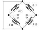
Figure T3.5
Expert Solution & Answer
Want to see the full answer?
Check out a sample textbook solution
Students have asked these similar questions
lonization energy of dopants in semiconductors
lonization energy of shallow donors and acceptors can be evaluated using
hydrogenic model:
lonization energy E Hion and orbital radius a, of hydrogen atom
Hydrogen Atom
moe4
EHion
= 13.6 eV a =
8ε²h²
Απερη
mee²
= 5.2918 x 10⁻¹¹ m
lonization energy Eion and orbital radius D,A of donors
and acceptors
electron
m* e4
Eion
=
~50 meV
8K² &²h²
4πεερη2
"D,A
1 nm
m*e²
Orbit of an electron bound to a
donor in a semiconductor crystal.
Energy levels of donors and acceptors
Conduction Band
↓
Ec
-Ed
Donor Level
Donor ionization energy
Acceptor ionization energy
Acceptor Level
Εα
Ev
Valence Band
Ionization energy of selected donors and acceptors in silicon
Donors
Acceptors
Dopant
Sb
P
As
B
Al In
Ionization energy, Ec-Ed or Ea-E, (meV) 39
44
54
45
57
160
Hydrogenic model of donors and acceptors
Calculate the ionization energies and orbit radii of donors and acceptors
in Si and Ge.
Dielectric constant of silicon is k = 11.7.
Dielectric constant of…
I need help in construct a method in matlab to find the voltage of VR1 to VR4, rhe current, and the power base on that circuit
Nominal or Theortical:
E1 = 3V , E2 = 9V, E3 = 1.5V
R1 =10Kohm, R2 =2Kohm, R3 =1Kohm, R4 =16Kohm
Procedure:-
1- Connect the cct. shown in fig.(2).
a
ADDs Ds
Fig.(2)
2-For resistive load, measure le output voltage by using oscilloscope; then sketch this
wave.
3- Measure the average values f VL and IL:
4- Repeat steps 2 & 3 but for RL load.
Report:-
1- Calculate the D.C. output vcl age theoretically and compare it with the test value.
2- Calculate the harmonic cont :nts of the load voltage, and explain how filter
components may be selected.
3- Compare between the three-phase half & full-wave uncontrolled bridge rectifier.
4- Draw the waveform for the c:t. shown in fig.(2) but after replaced Di and D3 by
thyristors with a = 30° and a2 = 90°
5- Draw the waveform for the cct. shown in fig.(2) but after replace the 6-diodes by 6-
thyristor.
6- Discuss your results. Draw the waves on graph paper
please
Please solve No. 4
and 5
Chapter 3 Solutions
Mastering Engineering with Pearson eText -- Standalone Access Card -- for Electrical Engineering: Principles & Applications
Ch. 3 - What is a dielectric material? Give two examples.Ch. 3 - Briefly discuss how current can flow “through” a...Ch. 3 - What current flows through an ideal capacitor if...Ch. 3 - Describe the internal construction of capacitors.Ch. 3 - A voltage of 50 V appears across a 10F capacitor....Ch. 3 - A 2000F capacitor, initially charged to 100V, is...Ch. 3 - A 5F Capacitor ischarged to 1000 V. Determine the...Ch. 3 - The voltage across a 10F capacitor is given by v...Ch. 3 - The voltage across a 1F capacitor is given by...Ch. 3 - Prior to t = 0, a 100F capacitance is uncharged...
Ch. 3 - The current through a 0.5F capacitor is shown in...Ch. 3 - Determine the capacitor voltage, power, and stored...Ch. 3 - A current given by i(t)=Imcos(t) flows through a...Ch. 3 - The current through a 3F capacitor is shown in...Ch. 3 - A constant (dc) current i(t)=3 mA flows into a 50F...Ch. 3 - The energy stored in a 2F capacitor is 200 J and...Ch. 3 - At t=t0 the voltage across a certain capacitance...Ch. 3 - An unusual capacitor has a capacitance that is a...Ch. 3 - For a resistor, what resistance corresponds to a...Ch. 3 - Suppose we have a very large capacitance (ideally,...Ch. 3 - We want to store sufficient energy in a 001-F...Ch. 3 - A 100F capacitor has a voltage given by v(t)=1010...Ch. 3 - How are capacitances combined in series and in...Ch. 3 - Find the equivalent capacitance for each of the...Ch. 3 - Find the equivalent capacitance between terminals...Ch. 3 - A network has a 5F capacitance in series with the...Ch. 3 - What are the minimum and maximum values of...Ch. 3 - Two initially uncharged capacitors C1=15F and...Ch. 3 - Suppose that we are designing a cardiac pacemaker...Ch. 3 - Suppose that we have two 100F capacitors One is...Ch. 3 - Determine the capacitance of a parallel-plate...Ch. 3 - A 100-pF capacitor is constructed of parallel...Ch. 3 - We have a parallel-plate capacitor with plates of...Ch. 3 - Suppose that we have a 1000-pF parallel-plate...Ch. 3 - Two 1F capacitors have an initial voltage of 100 V...Ch. 3 - Prob. 3.36PCh. 3 - Prob. 3.37PCh. 3 - A parallel-plate capacitor is used as a vibration...Ch. 3 - A 0.1F capacitor has a parasitic series resistance...Ch. 3 - Prob. 3.40PCh. 3 - Briefly discuss how inductors are constructed.Ch. 3 - The current flowing through an inductor is...Ch. 3 - If the current through an ideal inductor is...Ch. 3 - Briefly discuss the fluid-flow analogy for an...Ch. 3 - The current flowing through a 2-H inductance is...Ch. 3 - The current flowing through a 100-mH inductance is...Ch. 3 - The current flowing through a 2-H inductance is...Ch. 3 - The voltage across a 2-H inductance is shown in...Ch. 3 - The voltage across a 10 H inductance is given by...Ch. 3 - A 2-H inductance has i(0) = 0 and v(t)=texp(t) for...Ch. 3 - A constant voltage of 10V is applied to a 50H...Ch. 3 - At t = 0, the current flowing in a 05-H inductance...Ch. 3 - The current through a 100-mH inductance is given...Ch. 3 - Prior to t= 0, the current in a 2-H inductance is...Ch. 3 - At t= 0, a constant 5-V voltage source is applied...Ch. 3 - Prob. 3.56PCh. 3 - Al t= 5 s, the energy stored in a 2-H inductor is...Ch. 3 - What value of inductance (having zero initial...Ch. 3 - To what circuit element does a very large...Ch. 3 - The voltage across an inductance L is given by...Ch. 3 - Discuss how inductances are combined in series and...Ch. 3 - Determine the equivalent inductance for each of...Ch. 3 - Find the equivalent inductance for each of the...Ch. 3 - What is the maximum inductance that can be...Ch. 3 - Suppose we want to combine (in series or in...Ch. 3 - Prob. 3.66PCh. 3 - Two inductances L1=1H and L2=2H are connected in...Ch. 3 - A 10-mH inductor has a parasitic series resistance...Ch. 3 - Draw the equivalent circuit for a real inductor,...Ch. 3 - Suppose that the equivalent circuit shown in...Ch. 3 - Consider the circuit shown in Figure P3.71 in...Ch. 3 - The circuit shown in Figure P3.72 has...Ch. 3 - Describe briefly the physical basis for mutual...Ch. 3 - The mutually coupled inductances in Figure P3.74...Ch. 3 - Repeat Problem P3.74 with the dot placed at the...Ch. 3 - a. Derive an expression for the equivalent...Ch. 3 - Consider the parallel inductors shown in Figure...Ch. 3 - Consider the mutually coupled inductors shown in...Ch. 3 - Mutually coupled inductances have...Ch. 3 - The current through a 200-mH inductance is given...Ch. 3 - A 1-H inductance has iL(0)=0 and vL(t)=texp(t) for...Ch. 3 - The current flowing through a 10F capacitor having...Ch. 3 - Determine the equivalent capacitance Ceq for...Ch. 3 - A certain parallel-plate capacitor has plate...Ch. 3 - A 2-mH inductance has iab=0.3sin(2000t)A . Find an...Ch. 3 - Determine the equivalent inductance Leq between...Ch. 3 - Given that vc(t)=10sin(1000t)V , find vs(t)in the...Ch. 3 - Prob. 3.7PTCh. 3 - The current flowing through a 20F capacitor having...
Knowledge Booster


Learn more about
Need a deep-dive on the concept behind this application? Look no further. Learn more about this topic, electrical-engineering and related others by exploring similar questions and additional content below.Similar questions
- not use ai please chat gpt How to draw this in LtSpicearrow_forward4. Discussion: Compare between theoretical effect of KI at first order and second order systems regarding steady-state errors and transient responses with the practical In Experiment Integral Controllerarrow_forwardI would appreciate your help in solving the questions and drawing.arrow_forward
- 498 FET AMPLIFIERS AND SWITCHING CIRCUITS FIGURE 9-54 FIGURE 0.55 5. Identify the type of FET and its bias arrangement in Figure 9-54. Ideally, what is Vas? 6. Calculate the dc voltages from each terminal to ground for the FETs in Figure 9-54. +15 V -10 V +12 V 8 mA Ro 3 mA 1.0 ΚΩ Rp 1.5 ΚΩ Rp 6 mA R₁ 1.0 ΚΩ 10 ΚΩ RG * 10 ΜΩ RG 10 ΜΩ ww Rs R₂ • 330 Ω · 4.7 ΚΩ (a) (b) 7. Identify each characteristic curve in Figure 9-55 by the type of FET that it represents.arrow_forwardCan you help me achieve the requirements using Arduino? I have encountered some issues with these requirements. 1. Functionality:** The system must control 3 LEDS (Red, Green, and Blue) to produce at least 4 different lighting modes: a. **Mode 1: All LEDs blink simultaneously at 1-second intervals. b. Mode 2: LEDs blink in sequence (Red → Green → Blue) with a 500ms delay between each LED. c. **Mode 3:** LEDs fade in and out smoothly (PWM control) in the order Red Green → Blue. d. **Mode 4: Custom mode (e.g., random blinking or a pattern of your choice). 2. Constraints:** -Use only one push button to cycle through the modes. -The system must operate within a 5V power supply. -The total current drawn by the LEDs must not exceed 100mA. -Use resistors to limit the current through each LED appropriately. 3. Design Process:** -Analysis: Calculate the required resistor values for each LED to ensure they operate within their specified current limits. Synthesis: Develop a circuit schematic and…arrow_forwardnot use ai pleasearrow_forward
- Procedure:- 1- Connect the cct. shown in fig.(2). a ADDS DS Fig.(2) 2-For resistive load, measure le output voltage by using oscilloscope ;then sketch this wave. 3- Measure the average values ::f VL and IL: 4- Repeat steps 2 & 3 but for RL load. Report:- 1- Calculate the D.C. output vcl age theoretically and compare it with the test value. 2- Calculate the harmonic cont :nts of the load voltage, and explain how filter components may be selected. 3- Compare between the three-phase half & full-wave uncontrolled bridge rectifier. 4- Draw the waveform for the c:t. shown in fig.(2) but after replaced Di and D3 by thyristors with a 30° and a2 = 90° 5- Draw the waveform for the cct. shown in fig.(2) but after replace the 6-diodes by 6- thyristor. 6- Discuss your results. Please solve No. 4 and 5arrow_forwarda.) Sketch each of the following signals, and starting with the defining relation, finds its Fourier transform X (w) - a) x(t) = rect(t − 3) b) x(t)=3t rect(t) c) x(t) = 2te 3u1(t) d) x(t) = e−2|t| b.) Sketch the magnitude and phase spectrum for the four signals in Problem (a). c) Calculate energy using time-domain and frequency domain formulas for signals in Problem (a) and (b). Confirm Parseval's theorem using these calculations.arrow_forwardI need help in construct a method in matlab to find the voltage of VR1 to VR4, rhe current, and the power base on that circuit Nominal or Theortical: E1 = 3V , E2 = 9V, E3 = 1.5V R1 =10Kohm, R2 =2Kohm, R3 =1Kohm, R4 =16Kohmarrow_forward
- I have a question based on the mesh anaylsis, why does current around R1 and the same as R3?arrow_forward1. Compute the output signals S and T for the circuit. Input signals P = 1, Q = 1, and R = 1. C₁ P half-adder #1 R AND -S C₁₂ half-adder #2 2. Use 8-bit representations to compute the following sum. Show all work. 57+(-118) 3. Find a counterexample to show that the following statement is false: 1 Vx Є R, x>- χ T 4. Is the proposed negation correct? If yes, provide a sound reasoning. If not, provide a sound reasoning and write the correct negation. Statement: For all integers n, if n² is even then n is even. Negation: For all integers n, if n² is even then n is not even.arrow_forwardnot use aiarrow_forward
arrow_back_ios
SEE MORE QUESTIONS
arrow_forward_ios
Recommended textbooks for you
 Introductory Circuit Analysis (13th Edition)Electrical EngineeringISBN:9780133923605Author:Robert L. BoylestadPublisher:PEARSON
 Delmar's Standard Textbook Of ElectricityElectrical EngineeringISBN:9781337900348Author:Stephen L. HermanPublisher:Cengage Learning
 Programmable Logic ControllersElectrical EngineeringISBN:9780073373843Author:Frank D. PetruzellaPublisher:McGraw-Hill Education
 Fundamentals of Electric CircuitsElectrical EngineeringISBN:9780078028229Author:Charles K Alexander, Matthew SadikuPublisher:McGraw-Hill Education
 Electric Circuits. (11th Edition)Electrical EngineeringISBN:9780134746968Author:James W. Nilsson, Susan RiedelPublisher:PEARSON
 Engineering ElectromagneticsElectrical EngineeringISBN:9780078028151Author:Hayt, William H. (william Hart), Jr, BUCK, John A.Publisher:Mcgraw-hill Education,
Introductory Circuit Analysis (13th Edition)
Electrical Engineering
ISBN:9780133923605
Author:Robert L. Boylestad
Publisher:PEARSON
Delmar's Standard Textbook Of Electricity
Electrical Engineering
ISBN:9781337900348
Author:Stephen L. Herman
Publisher:Cengage Learning
Programmable Logic Controllers
Electrical Engineering
ISBN:9780073373843
Author:Frank D. Petruzella
Publisher:McGraw-Hill Education
Fundamentals of Electric Circuits
Electrical Engineering
ISBN:9780078028229
Author:Charles K Alexander, Matthew Sadiku
Publisher:McGraw-Hill Education
Electric Circuits. (11th Edition)
Electrical Engineering
ISBN:9780134746968
Author:James W. Nilsson, Susan Riedel
Publisher:PEARSON
Engineering Electromagnetics
Electrical Engineering
ISBN:9780078028151
Author:Hayt, William H. (william Hart), Jr, BUCK, John A.
Publisher:Mcgraw-hill Education,
02 - Sinusoidal AC Voltage Sources in Circuits, Part 1; Author: Math and Science;https://www.youtube.com/watch?v=8zMiIHVMfaw;License: Standard Youtube License