
Applied Statics and Strength of Materials (6th Edition)
6th Edition
ISBN: 9780133840544
Author: George F. Limbrunner, Craig D'Allaird, Leonard Spiegel
Publisher: PEARSON
expand_more
expand_more
format_list_bulleted
Videos
Textbook Question
Chapter 3, Problem 3.61SP
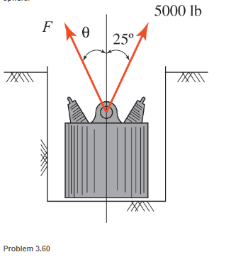
Refer to the diagram for Problem 3.60 /.  Assume that the transformer weights 6000 lb. determine θ and the magnitude of the force F so that the resultant of the lifting force (6000 lb) will act vertically upward.
Expert Solution & Answer
Want to see the full answer?
Check out a sample textbook solution
Students have asked these similar questions
My answers are incorrect
Picture
What is the weight of a 5-kg substance in N, kN, kg·m/s², kgf, Ibm-ft/s², and lbf?
The weight of a 5-kg substance in N is 49.05
N.
The weight of a 5-kg substance in kN is
KN.
The weight of a 5-kg substance in kg·m/s² is 49.05
kg-m/s².
The weight of a 5-kg substance in kgf is 5.0 kgf.
The weight of a 5-kg substance in Ibm-ft/s² is 11.02 lbm-ft/s².
The weight of a 5-kg substance in lbf is 11.023
lbf.
Chapter 3 Solutions
Applied Statics and Strength of Materials (6th Edition)
Ch. 3 - through 3.3 Determine the magnitude, direction,...Ch. 3 - Determine the magnitude, direction, and sense of...Ch. 3 - Determine the magnitude, direction, and sense of...Ch. 3 - Solve Problem 3.1 through 3.3 using the method of...Ch. 3 - Solve Problem 3.1 through 3.3 using the method of...Ch. 3 - through 3.6 Solve Problem 3.1 through 3.3 using...Ch. 3 - The 150-lb force shown is the resultant of two...Ch. 3 - Find the resultant force P exerted on the tree.Ch. 3 - Find the resultant force R exerted on the pole.Ch. 3 - Calculate the resultant force on the screw eye....
Ch. 3 - Determine the resultant of the coplanar concurrent...Ch. 3 - Use the parallelogram law to find the following...Ch. 3 - Prob. 3.13PCh. 3 - Determine the resultant of the coplanar concurrent...Ch. 3 - The resultant of the concurrent force system shown...Ch. 3 - Three force of 900 lb, 1000 lb, and 600 lb are...Ch. 3 - The four forces shown hade parallel lines of...Ch. 3 - Three coplanar concurrent forces act as shown. a....Ch. 3 - Four coplanar concurrent forces act as shown a....Ch. 3 - Determine the resultant of the four forces of...Ch. 3 - For the concrete wall and footing shown: a....Ch. 3 - Calculate the moment of the 550-lb force about...Ch. 3 - In Problem 3.22 , calculate the moment about point...Ch. 3 - Compute the moment about point A for the linkage...Ch. 3 - Compute the moment of the force F about point A...Ch. 3 - Determine the magnitude of the resultant of the...Ch. 3 - Determine the magnitude of the resultant of the...Ch. 3 - Determine the magnitude of the resultant of the...Ch. 3 - Determine the magnitude of the resultant of the...Ch. 3 - Determine the resultant and its location for the...Ch. 3 - Compute the magnitude, sense, and location of the...Ch. 3 - Compute the magnitude, sense, and location of the...Ch. 3 - Compute the magnitude and location of the...Ch. 3 - Determine the magnitude and location of the...Ch. 3 - Fresh water is impounded behind a dam to a height...Ch. 3 - Determine the magnitude and location of the...Ch. 3 - Determine the magnitude and location of the...Ch. 3 - Compute the magnitude and direction of the...Ch. 3 - Compute the magnitude and direction of the...Ch. 3 - Compute the magnitude and direction of the...Ch. 3 - A body is subjected to the following three...Ch. 3 - Determine the magnitude, direction, and sense of...Ch. 3 - Determine the magnitude, direction, and sense of...Ch. 3 - Determine the resultant of the load system shown....Ch. 3 - For the concrete structure shown, determine the...Ch. 3 - For the following computer problems, any...Ch. 3 - For the following computer problems, any...Ch. 3 - For the following computer problems, any...Ch. 3 - 3.49 Determine the magnitude, direction, and sense...Ch. 3 - The resultant and one-component force of a...Ch. 3 - The resultant force of a concurrent force system...Ch. 3 - Determine the magnitudes of forces P1 and P2 such...Ch. 3 - The resultant force of a concurrent force system...Ch. 3 - A hockey puck is acted on simultaneously by two...Ch. 3 - Determine the resultant force for each of the...Ch. 3 - Determine the resultant force for each of the...Ch. 3 - The resultant of the three concurrent forces shown...Ch. 3 - The transmission tower shown is subjected to a...Ch. 3 - A gravity-type masonry dam, as shown, depends on...Ch. 3 - The transfomer (as shown) must be lifted...Ch. 3 - Refer to the diagram for Problem 3.60 /. Assume...Ch. 3 - The plastic barrel tent anchor of Problem 2.11...Ch. 3 - Calculate the moment of the forces shown with...Ch. 3 - Determine the magnitude and location of the...Ch. 3 - Determine the moment (about point A) of the appied...Ch. 3 - The lift force on the wing of an aircraft is...Ch. 3 - A beam is subjected to distributed loads as shown....Ch. 3 - For the concrete gravity wall shown, determine the...Ch. 3 - Fresh water is impounded to a height of 8 ft...Ch. 3 - Plank, 2 in. by 10 in. in cross section and 5 ft...Ch. 3 - a. Compute the moment (about point A) of the...Ch. 3 - Determine the resultant of the three forces acting...Ch. 3 - a. Calculate the moments about points A and B due...Ch. 3 - Determine the magnitude of F1 and F2 shown such...Ch. 3 - Calculate the magnitude, direction, and sense of...
Knowledge Booster


Learn more about
Need a deep-dive on the concept behind this application? Look no further. Learn more about this topic, mechanical-engineering and related others by exploring similar questions and additional content below.Similar questions
- Mych CD 36280 kg. 0.36 givens Tesla truck frailer 2017 Model Vven 96154kph ronge 804,5km Cr Powertrain Across PHVAC rwheel 0.006 0.88 9M² 2 2kW 0.55M ng Zg Prated Trated Pair 20 0.95 1080 kW 1760 Nm 1,2 determine the battery energy required to meet the range when fully loaded determine the approximate time for the fully-loaded truck-trailor to accelerate from 0 to 60 mph while Ignoring vehicle load forcesarrow_forward12-217. The block B is sus- pended from a cable that is at- tached to the block at E, wraps around three pulleys, and is tied to the back of a truck. If the truck starts from rest when ID is zero, and moves forward with a constant acceleration of ap = 0.5 m/s², determine the speed of the block at D the instant x = 2 m. Neglect the size of the pulleys in the calcu- lation. When xƊ = 0, yc = 5 m, so that points C and D are at the Prob. 12-217 5 m yc =2M Xparrow_forwardsolve both and show matlab code auto controlsarrow_forward
- 12-82. The roller coaster car trav- els down the helical path at con- stant speed such that the paramet- ric equations that define its posi- tion are x = c sin kt, y = c cos kt, z = h - bt, where c, h, and b are constants. Determine the mag- nitudes of its velocity and accelera- tion. Prob. 12-82 Narrow_forwardGiven: = refueling Powertran SOURCE EMISSIONS vehide eff eff gasoline 266g co₂/kwh- HEV 0.90 0.285 FLgrid 411ilg Co₂/kWh 41111gCo₂/kWh EV 0.85 0.80 Production 11x10% og CO₂ 13.7 x 10°g CO₂ A) Calculate the breakeven pont (in km driven) for a EV against on HEV in Florida of 0.1kWh/kM Use a drive cycle conversion 5) How efficient would the powertrain of the HEV in this example have to be to break even with an EV in Florida after 150,000 Miles of service (240,000) km Is it plausible to achieve the answer from pert b Consideans the HaXINERY theoretical efficiency of the Carnot cycle is 5020 and there are additional losses of the transMISSION :- 90% efficiency ? c A what do you conclude is the leading factor in why EVs are less emissive than ICE,arrow_forwardsolve autocontrolsarrow_forward
- Problem 3.21P: Air at 100F(38C) db,65F(18C) wb, and sea-level pressure is humidified adiabatically with steam. The steam supplied contains 20 percent moisture(quality of 0.80) at 14.7psia(101.3kpa). The air is humidified to 60 percent relative humidity. Find the dry bulb temperature of the humidified air using (a)chart 1a or 1b and (b) the program PSYCH.arrow_forwardPUNTO 4. calculate their DoF using Gruebler's formula. PUNTO 5. Groundarrow_forwardPUNTO 2. PUNTO 3. calculate their DoF using Gruebler's formula. III IAarrow_forward
- calculate their DoF using Gruebler's formula. PUNTO 6. PUNTO 7. (Ctrl)arrow_forwardA pump delivering 230 lps of water at 30C has a 300-mm diameter suction pipe and a 254-mm diameter discharge pipe as shown in the figure. The suction pipe is 3.5 m long and the discharge pipe is 23 m long, both pipe's materials are cast iron. The water is delivered 16m above the intake water level. Considering head losses in fittings, valves, and major head loss. a) Find the total dynamic head which the pump must supply. b)It the pump mechanical efficiency is 68%, and the motor efficiency is 90%, determine the power rating of the motor in hp.given that: summation of K gate valve = 0.25check valve=390 degree elbow= 0.75foot valve= 0.78arrow_forwardA pump delivering 230 lps of water at 30C has a 300-mm diameter suction pipe and a 254-mm diameter discharge pipe as shown in the figure. The suction pipe is 3.5 m long and the discharge pipe is 23 m long, both pipe's materials are cast iron. The water is delivered 16m above the intake water level. Considering head losses in fittings, valves, and major head loss. a) Find the total dynamic head which the pump must supply. b)It the pump mechanical efficiency is 68%, and the motor efficiency is 90%, determine the power rating of the motor in hp.arrow_forward
arrow_back_ios
SEE MORE QUESTIONS
arrow_forward_ios
Recommended textbooks for you
 International Edition---engineering Mechanics: St...Mechanical EngineeringISBN:9781305501607Author:Andrew Pytel And Jaan KiusalaasPublisher:CENGAGE L
International Edition---engineering Mechanics: St...
Mechanical Engineering
ISBN:9781305501607
Author:Andrew Pytel And Jaan Kiusalaas
Publisher:CENGAGE L
How to balance a see saw using moments example problem; Author: Engineer4Free;https://www.youtube.com/watch?v=d7tX37j-iHU;License: Standard Youtube License