
Applied Statics and Strength of Materials (6th Edition)
6th Edition
ISBN: 9780133840544
Author: George F. Limbrunner, Craig D'Allaird, Leonard Spiegel
Publisher: PEARSON
expand_more
expand_more
format_list_bulleted
Concept explainers
Videos
Textbook Question
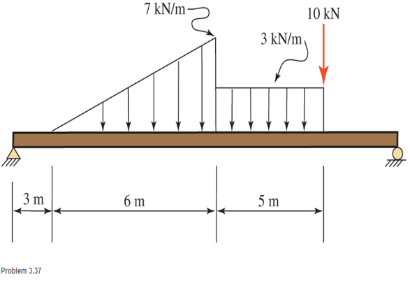
Chapter 3, Problem 3.37P
Determine the magnitude and location of the resultant for the load system shown.
Expert Solution & Answer

Learn your wayIncludes step-by-step video

schedule07:45
Students have asked these similar questions
For the walking-beam mechanism shown in Figure 3, find and plot the x and y coordinates of the
position of the coupler point P for one complete revolution of the crank O2A. Use the coordinate
system shown in Figure 3. Hint: Calculate them first with respect to the ground link 0204 and
then transform them into the global XY coordinate system.
y
-1.75
Ꮎ
Ꮎ
4
= 2.33
0242.22
L4
x
AP = 3.06
L2 = 1.0
W2
31°
B
03 L3 = 2.06
P
1
8
5
.06
6
7
P'
The link lengths, gear ratio (2), phase angle (Ø), and the value of 02 for some geared five bar
linkages are defined in Table 2. The linkage configuration and terminology are shown in Figure
2. For the rows assigned, find all possible solutions for angles 03 and 04 by the vector loop
method. Show your work in details: vector loop, vector equations, solution procedure.
Table 2
Row
Link 1 Link 2
Link 3
Link 4
Link 5
λ
Φ
Ө
a
6
1
7
9
4
2
30°
60°
P
y 4
YA
B
b
R4
R3
YA
A
Gear ratio:
a
02
d
05
r5
R5
R2
Phase angle: = 0₂-202
R1
05
02
r2
Figure 2.
04
X
Problem 4
A .025 lb bullet C is fired at end B of the 15-lb slender bar AB. The
bar is initially at rest, and the initial velocity of the bullet is 1500 ft/s
as shown. Assuming that the bullet becomes embedded in the bar,
find (a) the angular velocity @2 of the bar immediately after impact,
and (b) the percentage loss of kinetic energy as a result of the impact.
(c) After the impact, does the bar swing up 90° and reach the
horizontal? If it does, what is its angular velocity at this point?
Answers: (a). @2=1.6 rad/s; (b). 99.6% loss
=
(c). Ah2 0.212 ft. The bar does not reach horizontal.
y
X
4 ft
15 lb
V₁
1500 ft/s
0.025 lb
C
30°7
B
A
Chapter 3 Solutions
Applied Statics and Strength of Materials (6th Edition)
Ch. 3 - through 3.3 Determine the magnitude, direction,...Ch. 3 - Determine the magnitude, direction, and sense of...Ch. 3 - Determine the magnitude, direction, and sense of...Ch. 3 - Solve Problem 3.1 through 3.3 using the method of...Ch. 3 - Solve Problem 3.1 through 3.3 using the method of...Ch. 3 - through 3.6 Solve Problem 3.1 through 3.3 using...Ch. 3 - The 150-lb force shown is the resultant of two...Ch. 3 - Find the resultant force P exerted on the tree.Ch. 3 - Find the resultant force R exerted on the pole.Ch. 3 - Calculate the resultant force on the screw eye....
Ch. 3 - Determine the resultant of the coplanar concurrent...Ch. 3 - Use the parallelogram law to find the following...Ch. 3 - Prob. 3.13PCh. 3 - Determine the resultant of the coplanar concurrent...Ch. 3 - The resultant of the concurrent force system shown...Ch. 3 - Three force of 900 lb, 1000 lb, and 600 lb are...Ch. 3 - The four forces shown hade parallel lines of...Ch. 3 - Three coplanar concurrent forces act as shown. a....Ch. 3 - Four coplanar concurrent forces act as shown a....Ch. 3 - Determine the resultant of the four forces of...Ch. 3 - For the concrete wall and footing shown: a....Ch. 3 - Calculate the moment of the 550-lb force about...Ch. 3 - In Problem 3.22 , calculate the moment about point...Ch. 3 - Compute the moment about point A for the linkage...Ch. 3 - Compute the moment of the force F about point A...Ch. 3 - Determine the magnitude of the resultant of the...Ch. 3 - Determine the magnitude of the resultant of the...Ch. 3 - Determine the magnitude of the resultant of the...Ch. 3 - Determine the magnitude of the resultant of the...Ch. 3 - Determine the resultant and its location for the...Ch. 3 - Compute the magnitude, sense, and location of the...Ch. 3 - Compute the magnitude, sense, and location of the...Ch. 3 - Compute the magnitude and location of the...Ch. 3 - Determine the magnitude and location of the...Ch. 3 - Fresh water is impounded behind a dam to a height...Ch. 3 - Determine the magnitude and location of the...Ch. 3 - Determine the magnitude and location of the...Ch. 3 - Compute the magnitude and direction of the...Ch. 3 - Compute the magnitude and direction of the...Ch. 3 - Compute the magnitude and direction of the...Ch. 3 - A body is subjected to the following three...Ch. 3 - Determine the magnitude, direction, and sense of...Ch. 3 - Determine the magnitude, direction, and sense of...Ch. 3 - Determine the resultant of the load system shown....Ch. 3 - For the concrete structure shown, determine the...Ch. 3 - For the following computer problems, any...Ch. 3 - For the following computer problems, any...Ch. 3 - For the following computer problems, any...Ch. 3 - 3.49 Determine the magnitude, direction, and sense...Ch. 3 - The resultant and one-component force of a...Ch. 3 - The resultant force of a concurrent force system...Ch. 3 - Determine the magnitudes of forces P1 and P2 such...Ch. 3 - The resultant force of a concurrent force system...Ch. 3 - A hockey puck is acted on simultaneously by two...Ch. 3 - Determine the resultant force for each of the...Ch. 3 - Determine the resultant force for each of the...Ch. 3 - The resultant of the three concurrent forces shown...Ch. 3 - The transmission tower shown is subjected to a...Ch. 3 - A gravity-type masonry dam, as shown, depends on...Ch. 3 - The transfomer (as shown) must be lifted...Ch. 3 - Refer to the diagram for Problem 3.60 /. Assume...Ch. 3 - The plastic barrel tent anchor of Problem 2.11...Ch. 3 - Calculate the moment of the forces shown with...Ch. 3 - Determine the magnitude and location of the...Ch. 3 - Determine the moment (about point A) of the appied...Ch. 3 - The lift force on the wing of an aircraft is...Ch. 3 - A beam is subjected to distributed loads as shown....Ch. 3 - For the concrete gravity wall shown, determine the...Ch. 3 - Fresh water is impounded to a height of 8 ft...Ch. 3 - Plank, 2 in. by 10 in. in cross section and 5 ft...Ch. 3 - a. Compute the moment (about point A) of the...Ch. 3 - Determine the resultant of the three forces acting...Ch. 3 - a. Calculate the moments about points A and B due...Ch. 3 - Determine the magnitude of F1 and F2 shown such...Ch. 3 - Calculate the magnitude, direction, and sense of...
Additional Engineering Textbook Solutions
Find more solutions based on key concepts
1. Read the problem statement. 2. Formulate the algorithm using pseudocode and top-down, stepwise refinement. 3...
Java How to Program, Early Objects (11th Edition) (Deitel: How to Program)
Big data Big data describes datasets with huge volumes that are beyond the ability of typical database manageme...
Management Information Systems: Managing The Digital Firm (16th Edition)
A(n) _____ is a set of well-defined steps for performing a task or solving a problem.
Starting Out With Visual Basic (8th Edition)
Find the errors in the following code: 1. // Warning! This code contains ERRORS! if (x = = 1); y = 2; else if (...
Starting Out with Java: From Control Structures through Objects (7th Edition) (What's New in Computer Science)
Fill in the blanks in each of the following statements: A relation that has no partial functional dependencies ...
Modern Database Management
Write a Vole program that places 0s in all the memory cells from address 0xA0 through 0xC0 but is small enough ...
Computer Science: An Overview (13th Edition) (What's New in Computer Science)
Knowledge Booster


Learn more about
Need a deep-dive on the concept behind this application? Look no further. Learn more about this topic, mechanical-engineering and related others by exploring similar questions and additional content below.Similar questions
- subject: combustion please include complete solution, no rounding off, with diagram/explanation etc. In a joule cycle, intake of the compressor is 40,000 cfm at 0.3 psig and 90 deg F. The compression ratio is 6.0 and the inlet temperature at the turbine portion is 1900R while at the exit, it is 15 psi. Calculate for the back work ratio in percent.arrow_forwardsubject: combustion please include complete solution, no rounding off, with diagram/explanation etc. A gasoline engine, utilizing cold air, recorded a work of 431 BTU/lb at a maximum temperature of 3,273 K and 1112 deg F temperature at the beginning of constant volume heat addition. What is the compression ratio?arrow_forwardsubject: combustion please do step by step solution and no rounding off, complete solution with diagram/explanation if needed etc. thank you! Air enters the compressor at 101,320 Pascals, 305.15K, and leaves at a pressure of 0.808MPa. The air is heated to 990.15K in the combustion chamber. For a net output of 2,125,000 Watts, find the rate of flow of air per second.arrow_forward
- The link lengths and the value of 2 and offset for some fourbar crank-slide linkages are defined in Table 1. The linkage configuration and terminology are shown in Figure 1. For the rows assigned, find (a) all possible solutions for angle & and slider position d by vector loop method. (b) the transmission angle corresponding to angle 03. (Hint: Treat the vector R4 as virtual rocker) Show your work in details: vector loop, vector equations, solution procedure. Table 1 Row Link 2 Link 3 Offset Ө a 1.4 4 1 45° b 3 8 2 -30° C 5 20 -5 225° 03 slider axis B X offset Link 2 A R3 Link 3 R4 04 R2 02 R1 d Figure 1. Xarrow_forward4. Two links made of heat treated 6061 aluminum (Sy = 276 MPa, Sys = 160 MPa) are pinned together using a steel dowel pin (Sy = 1398 MPa, Sys = 806 MPa) as shown below. The links are to support a load P with a factor of safety of at least 2.0. Determine if the link will fail first by tearout, direct shear of the pin, bearing stress on the link, or tensile stress at section AA. (Hint: find the load P for each case and choose the case that gives the smallest load.) P 8 mm P 8 mm ¡+A 3 mm →A 10 mm Parrow_forward1. For a feature other than a sphere, circularity is where: A. The axis is a straight line B. The modifier is specified with a size dimension C. All points of the surface intersected by any plane perpendicular to an axis or spine (curved line) are equidistant from that axis or spine D. All points of the surface intersected by any plane passing through a common center are equidistant from that center 2. What type of variation is limited by a circularity toler- ance zone? A. Ovality B. Tapering C. Bending D. Warping 3. How does the Rule #1 boundary affect the application of a circularity tolerance? A. The modifier must be used. B. The feature control frame must be placed next to the size dimension. C. The circularity tolerance value must be less than the limits of size tolerance. D. Circularity cannot be applied where a Rule #1 boundary exists. 4. A circularity tolerance may use a modifier. A. Ø B. F C. M D. ℗ 5. A real-world application for a circularity tolerance is: A. Assembly (i.e.,…arrow_forward
- 3. A steel bar is pinned to a vertical support column by a 10 mm diameter hardened dowel pin, Figure 1. For P = 7500 N, find: a. the shear stress in the pin, b. the direct bearing stress on the hole in the bar, c. the minimum value of d to prevent tearout failure if the steel bar has a shear strength of 175 MPa. support column pin bar thickness of bar = 8 mm h d 150 mmarrow_forwardA press that delivers 115 strokes per minute, each stroke providing a force of 7826 N throughout a distance of 18 mm. The press efficiency is 90% and is driven by a 1749-rpm motor. Determine average torque that must be provided by the motor in the units of N-m.arrow_forward·3) find the force (P) for the figures (1) and (2) 15cm 10cm 15 h=10mm h2=6mm // Call = 90 N/2 P Agate Fig (i) Ans: 1)P=112614N 2) P=1956.5 N 25cm 25 cm الفترة أو الحجم تمر بالتي عثر اكو تورشن (ک Fig (2) h₁ = 10mm 42=6mm Cmarrow_forward
arrow_back_ios
SEE MORE QUESTIONS
arrow_forward_ios
Recommended textbooks for you
 International Edition---engineering Mechanics: St...Mechanical EngineeringISBN:9781305501607Author:Andrew Pytel And Jaan KiusalaasPublisher:CENGAGE L
International Edition---engineering Mechanics: St...
Mechanical Engineering
ISBN:9781305501607
Author:Andrew Pytel And Jaan Kiusalaas
Publisher:CENGAGE L
Types Of loads - Engineering Mechanics | Abhishek Explained; Author: Prime Course;https://www.youtube.com/watch?v=4JVoL9wb5yM;License: Standard YouTube License, CC-BY