
Applied Statics and Strength of Materials (6th Edition)
6th Edition
ISBN: 9780133840544
Author: George F. Limbrunner, Craig D'Allaird, Leonard Spiegel
Publisher: PEARSON
expand_more
expand_more
format_list_bulleted
Concept explainers
Videos
Textbook Question
thumb_up100%
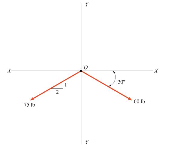
Chapter 3, Problem 3.6P
through 3.6 Solve Problem 3.1  through 3.3
  using the method of components.
Expert Solution & Answer

Learn your wayIncludes step-by-step video

schedule06:07
Students have asked these similar questions
using the theorem of three moments, find all the moments, I need concise calculations only
Practise question need help on
Can you show explaination and working. The answer from the text book is Q=5.03 X 10^-3
Chapter 3 Solutions
Applied Statics and Strength of Materials (6th Edition)
Ch. 3 - through 3.3 Determine the magnitude, direction,...Ch. 3 - Determine the magnitude, direction, and sense of...Ch. 3 - Determine the magnitude, direction, and sense of...Ch. 3 - Solve Problem 3.1 through 3.3 using the method of...Ch. 3 - Solve Problem 3.1 through 3.3 using the method of...Ch. 3 - through 3.6 Solve Problem 3.1 through 3.3 using...Ch. 3 - The 150-lb force shown is the resultant of two...Ch. 3 - Find the resultant force P exerted on the tree.Ch. 3 - Find the resultant force R exerted on the pole.Ch. 3 - Calculate the resultant force on the screw eye....
Ch. 3 - Determine the resultant of the coplanar concurrent...Ch. 3 - Use the parallelogram law to find the following...Ch. 3 - Prob. 3.13PCh. 3 - Determine the resultant of the coplanar concurrent...Ch. 3 - The resultant of the concurrent force system shown...Ch. 3 - Three force of 900 lb, 1000 lb, and 600 lb are...Ch. 3 - The four forces shown hade parallel lines of...Ch. 3 - Three coplanar concurrent forces act as shown. a....Ch. 3 - Four coplanar concurrent forces act as shown a....Ch. 3 - Determine the resultant of the four forces of...Ch. 3 - For the concrete wall and footing shown: a....Ch. 3 - Calculate the moment of the 550-lb force about...Ch. 3 - In Problem 3.22 , calculate the moment about point...Ch. 3 - Compute the moment about point A for the linkage...Ch. 3 - Compute the moment of the force F about point A...Ch. 3 - Determine the magnitude of the resultant of the...Ch. 3 - Determine the magnitude of the resultant of the...Ch. 3 - Determine the magnitude of the resultant of the...Ch. 3 - Determine the magnitude of the resultant of the...Ch. 3 - Determine the resultant and its location for the...Ch. 3 - Compute the magnitude, sense, and location of the...Ch. 3 - Compute the magnitude, sense, and location of the...Ch. 3 - Compute the magnitude and location of the...Ch. 3 - Determine the magnitude and location of the...Ch. 3 - Fresh water is impounded behind a dam to a height...Ch. 3 - Determine the magnitude and location of the...Ch. 3 - Determine the magnitude and location of the...Ch. 3 - Compute the magnitude and direction of the...Ch. 3 - Compute the magnitude and direction of the...Ch. 3 - Compute the magnitude and direction of the...Ch. 3 - A body is subjected to the following three...Ch. 3 - Determine the magnitude, direction, and sense of...Ch. 3 - Determine the magnitude, direction, and sense of...Ch. 3 - Determine the resultant of the load system shown....Ch. 3 - For the concrete structure shown, determine the...Ch. 3 - For the following computer problems, any...Ch. 3 - For the following computer problems, any...Ch. 3 - For the following computer problems, any...Ch. 3 - 3.49 Determine the magnitude, direction, and sense...Ch. 3 - The resultant and one-component force of a...Ch. 3 - The resultant force of a concurrent force system...Ch. 3 - Determine the magnitudes of forces P1 and P2 such...Ch. 3 - The resultant force of a concurrent force system...Ch. 3 - A hockey puck is acted on simultaneously by two...Ch. 3 - Determine the resultant force for each of the...Ch. 3 - Determine the resultant force for each of the...Ch. 3 - The resultant of the three concurrent forces shown...Ch. 3 - The transmission tower shown is subjected to a...Ch. 3 - A gravity-type masonry dam, as shown, depends on...Ch. 3 - The transfomer (as shown) must be lifted...Ch. 3 - Refer to the diagram for Problem 3.60 /. Assume...Ch. 3 - The plastic barrel tent anchor of Problem 2.11...Ch. 3 - Calculate the moment of the forces shown with...Ch. 3 - Determine the magnitude and location of the...Ch. 3 - Determine the moment (about point A) of the appied...Ch. 3 - The lift force on the wing of an aircraft is...Ch. 3 - A beam is subjected to distributed loads as shown....Ch. 3 - For the concrete gravity wall shown, determine the...Ch. 3 - Fresh water is impounded to a height of 8 ft...Ch. 3 - Plank, 2 in. by 10 in. in cross section and 5 ft...Ch. 3 - a. Compute the moment (about point A) of the...Ch. 3 - Determine the resultant of the three forces acting...Ch. 3 - a. Calculate the moments about points A and B due...Ch. 3 - Determine the magnitude of F1 and F2 shown such...Ch. 3 - Calculate the magnitude, direction, and sense of...
Additional Engineering Textbook Solutions
Find more solutions based on key concepts
Show that for circular motion, force = mass * velocity squared/radius.
Thinking Like an Engineer: An Active Learning Approach (4th Edition)
Determine the maximum force P that can be applied without causing movement of the 250-lb crate that has a cente...
INTERNATIONAL EDITION---Engineering Mechanics: Statics, 14th edition (SI unit)
software is generally feature complete, (supposedly) bug free and ready for use by the community.
Java How to Program, Early Objects (11th Edition) (Deitel: How to Program)
Look at the following code, which is the first line of a class definition: public class Tiger extends Felis In ...
Starting Out with Java: From Control Structures through Objects (7th Edition) (What's New in Computer Science)
CONCEPT QUESTIONS
15.CQ3 The ball rolls without slipping on the fixed surface as shown. What is the direction ...
Vector Mechanics for Engineers: Statics and Dynamics
Write a program that requests the current time and a waiting time as two integers for the number of hours and t...
Problem Solving with C++ (10th Edition)
Knowledge Booster


Learn more about
Need a deep-dive on the concept behind this application? Look no further. Learn more about this topic, mechanical-engineering and related others by exploring similar questions and additional content below.Similar questions
- practise questionarrow_forwardCan you provide steps and an explaination on how the height value to calculate the Pressure at point B is (-5-3.5) and the solution is 86.4kPa.arrow_forwardPROBLEM 3.46 The solid cylindrical rod BC of length L = 600 mm is attached to the rigid lever AB of length a = 380 mm and to the support at C. When a 500 N force P is applied at A, design specifications require that the displacement of A not exceed 25 mm when a 500 N force P is applied at A For the material indicated determine the required diameter of the rod. Aluminium: Tall = 65 MPa, G = 27 GPa. Aarrow_forward
- Find the equivalent mass of the rocker arm assembly with respect to the x coordinate. k₁ mi m2 k₁arrow_forward2. Figure below shows a U-tube manometer open at both ends and containing a column of liquid mercury of length l and specific weight y. Considering a small displacement x of the manometer meniscus from its equilibrium position (or datum), determine the equivalent spring constant associated with the restoring force. Datum Area, Aarrow_forward1. The consequences of a head-on collision of two automobiles can be studied by considering the impact of the automobile on a barrier, as shown in figure below. Construct a mathematical model (i.e., draw the diagram) by considering the masses of the automobile body, engine, transmission, and suspension and the elasticity of the bumpers, radiator, sheet metal body, driveline, and engine mounts.arrow_forward
- 3.) 15.40 – Collar B moves up at constant velocity vB = 1.5 m/s. Rod AB has length = 1.2 m. The incline is at angle = 25°. Compute an expression for the angular velocity of rod AB, ė and the velocity of end A of the rod (✓✓) as a function of v₂,1,0,0. Then compute numerical answers for ȧ & y_ with 0 = 50°.arrow_forward2.) 15.12 The assembly shown consists of the straight rod ABC which passes through and is welded to the grectangular plate DEFH. The assembly rotates about the axis AC with a constant angular velocity of 9 rad/s. Knowing that the motion when viewed from C is counterclockwise, determine the velocity and acceleration of corner F.arrow_forward500 Q3: The attachment shown in Fig.3 is made of 1040 HR. The static force is 30 kN. Specify the weldment (give the pattern, electrode number, type of weld, length of weld, and leg size). Fig. 3 All dimension in mm 30 kN 100 (10 Marks)arrow_forward
- (read image) (answer given)arrow_forwardA cylinder and a disk are used as pulleys, as shown in the figure. Using the data given in the figure, if a body of mass m = 3 kg is released from rest after falling a height h 1.5 m, find: a) The velocity of the body. b) The angular velocity of the disk. c) The number of revolutions the cylinder has made. T₁ F Rd = 0.2 m md = 2 kg T T₂1 Rc = 0.4 m mc = 5 kg ☐ m = 3 kgarrow_forward(read image) (answer given)arrow_forward
arrow_back_ios
SEE MORE QUESTIONS
arrow_forward_ios
Recommended textbooks for you
 Mechanics of Materials (MindTap Course List)Mechanical EngineeringISBN:9781337093347Author:Barry J. Goodno, James M. GerePublisher:Cengage Learning
 Principles of Heat Transfer (Activate Learning wi...Mechanical EngineeringISBN:9781305387102Author:Kreith, Frank; Manglik, Raj M.Publisher:Cengage Learning
Mechanics of Materials (MindTap Course List)
Mechanical Engineering
ISBN:9781337093347
Author:Barry J. Goodno, James M. Gere
Publisher:Cengage Learning
Principles of Heat Transfer (Activate Learning wi...
Mechanical Engineering
ISBN:9781305387102
Author:Kreith, Frank; Manglik, Raj M.
Publisher:Cengage Learning
Solids: Lesson 53 - Slope and Deflection of Beams Intro; Author: Jeff Hanson;https://www.youtube.com/watch?v=I7lTq68JRmY;License: Standard YouTube License, CC-BY